


Chapter 5 Input/Output Interfaces
5-8 Compaq iPAQ Family of Internet Devices
First Edition – March 2000
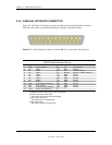
5.5 PARALLEL INTERFACE
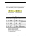
The legacy-light models include a parallel interface for connection to a peripheral device that has
a compatible interface, the most common being a printer. The parallel interface function is
integrated into theLPC47B277 I/O controller component and provides bi-directional 8-bit
parallel data transfers with a peripheral device. The parallel interface supports three main
modes of operation:
♦
Standard Parallel Port (SPP) mode
♦
Enhanced Parallel Port (EPP) mode
♦
Extended Capabilities Port (ECP) mode
These three modes (and their submodes) provide complete support as specified for an IEEE 1284
parallel port.
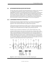
5.5.1 STANDARD PARALLEL PORT MODE
The Standard Parallel Port (SPP) mode uses software-based protocol and includes two sub-modes
of operation, compatible and extended, both of which can provide data transfers up to 150 KB/s.
In the compatible mode, CPU write data is simply presented on the eight data lines. A CPU read
of the parallel port yields the last data byte that was written.
The following steps define the standard procedure for communicating with a printing device:
1. The system checks the Printer Status register. If the Busy, Paper Out, or Printer Fault signals
are indicated as being active, the system either waits for a status change or generates an error
message.
2. The system sends a byte of data to the Printer Data register, then pulses the printer STROBE
signal (through the Printer Control register) for at least 500 ns.
3. The system then monitors the Printer Status register for acknowledgment of the data byte
before sending the next byte.
In extended mode, a direction control bit (CTR 37Ah, bit <5>) controls the latching of output
data while allowing a CPU read to fetch data present on the data lines, thereby providing bi-
directional parallel transfers to occur.
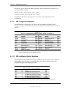
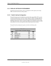
The SPP mode uses three registers for operation: the Data register (DTR), the Status register
(STR) and the Control register (CTR). Address decoding in SPP mode includes address lines A0
and A1.