


Technical Reference Guide
Compaq iPAQ Family of Internet Devices
First Edition - March 2000
5-3
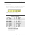
5.2.2 IDE CONNECTOR
This system uses a standard 40-pin connector for the primary IDE device and connects (via a
cable) to the hard drive installed in the right side drive bay. Note that some signals are re-defined
for UATA/33 and UATA/66 modes, which require a special 80-conductor cable (supplied)
designed to reduce cross-talk. Device power is supplied through a separate connector.
Figure 5-1.
40-Pin Primary IDE Connector (on system board).
Table 5–3
. 40-Pin Primary IDE Connector Pinout
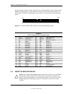
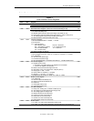
Table 5-3.
40-Pin Primary IDE Connector Pinout
Pin Signal Description Pin Signal Description
1 RESET- Reset 21 DRQ DMA Request
2 GND Ground 22 GND Ground
3 DD7 Data Bit <7> 23 IOW- I/O Write [1]
4 DD8 Data Bit <8> 24 GND Ground
5 DD6 Data Bit <6> 25 IOR- I/O Read [2]
6 DD9 Data Bit <9> 26 GND Ground
7 DD5 Data Bit <5> 27 IORDY I/O Channel Ready [3]
8 DD10 Data Bit <10> 28 CSEL Cable Select
9 DD4 Data Bit <4> 29 DAK- DMA Acknowledge
10 DD11 Data Bit <11> 30 GND Ground
11 DD3 Data Bit <3> 31 IRQn Interrupt Request [4]
12 DD12 Data Bit <12> 32 IO16- 16-bit I/O
13 DD2 Data Bit <2> 33 DA1 Address 1
14 DD13 Data Bit <13> 34 DSKPDIAG Pass Diagnostics
15 DD1 Data Bit <1> 35 DA0 Address 0
16 DD14 Data Bit <14> 36 DA2 Address 2
17 DD0 Data Bit <0> 37 CS0- Chip Select
18 DD15 Data Bit <15> 38 CS1- Chip Select
19 GND Ground 39 HDACTIVE- Drive Active (front panel LED) [5]
20 -- Key 40 GND Ground
NOTES:
[1] On UATA/33 and /66 modes, re-defined as STOP.
[2] On UATA/33 and /66 mode reads, re-defined as DMARDY-.
On UATA/33 and /66 mode writes, re-defined as STROBE.
[3] On UATA/33 and /66 mode reads, re-defined as STROBE-.
On UATA/33 and /66 mode writes, re-defined as DMARDY-.
[4] Primary connector wired to IRQ14, secondary connector wired to IRQ15.
[5] Pin 39 is used for spindle sync and drive activity (becomes SPSYNC/DACT-)
when synchronous drives are connected.