


Technical Reference Guide
Compaq iPAQ Family of Internet Devices
First Edition - March 2000
4-13
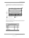
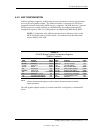
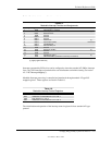
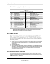
Table 4-5.
Maskable Interrupt Priorities and Assignments
Table 4-5.
Maskable Interrupt Priorities and Assignments
Priority Signal Label Source (Typical) Notes
1 IRQ0 Interval timer 1, counter 0
2 IRQ1 PS/2 Keyboard [1]
3 IRQ8- Real-time clock
4 IRQ9 Unused
5 IRQ10 Unused
6 IRQ11 Unused
7 IRQ12 PS/2 Mouse [1]
8 IRQ13 Coprocessor (math)
9 IRQ14 IDE primary I/F
10 IRQ15 IDE secondary I/F
11 IRQ3 Unused
12 IRQ4 Serial port (COM1) [1]
13 IRQ5 Unused
14 IRQ6 Unused
15 IRQ7 Parallel port (LPT1) [1]
-- IRQ2 NOT AVAILABLE (Cascade from interrupt controller 2)
NOTE:
[1] Legacy-light models only
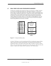
Interrupts generated by PCI devices can be configured to share the standard AT (IRQn) interrupt
lines. Also, PCI interrupts are hardwired for even distribution to minimize latency (see section
4.2.2 “PCI Interrupt Mapping”).
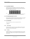
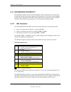
Maskable Interrupt processing is controlled and monitored through standard AT-type I/O-
mapped registers. These registers are listed in Table 4-6.
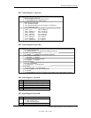
Table 4-6.
Maskable Interrupt Control Registers
Table 4-6.
Maskable Interrupt Control Registers
I/O Port Register
020h Base Address, Int. Cntlr. 1
021h Initialization Command Word 2-4, Int. Cntlr. 1
0A0h Base Address, Int. Cntlr. 2
0A1h Initialization Command Word 2-4, Int. Cntlr. 2
The initialization and operation of the interrupt control registers follows standard AT-type
protocol.