


System Overview 1-11
system board, and fan rpm; and supporting the SMB_ALERT protocol used by
the server management bus.
The PSPB connects to the power supplies through short harnesses that attach
to the back of the power supply cages. The PSPB is attached to the side wall of
the computer behind the external drive cage and is oriented in parallel with the
system board. For information on removing and replacing the PSPB, see
“Power-Supply Paralleling Board” in Chapter 4.
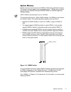
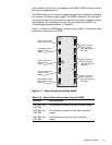
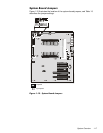
Figure 1-7 shows the PSPB power connector layout; Table 1-2 shows the cable
connections made from the PSPB.
)LJXUH3RZHU6XSSO\3DUDOOHOLQJ%RDUG
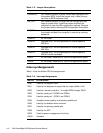
7DEOH3RZHU&DEOH&RQQHFWLRQV)URPWKH363%
&RQQHFWRU &DEOH&RQQHFWLRQ
PS1_PB1 and
PS1_PB2
To the power connector on the first power supply
PS2_PB1 and
PS2_PB2
To the power connector on the second power
supply
PS3_PB1 and
PS3_PB2
To the power connector on the third power
supply
system-board power
cable connector
(PWR2)
system-board power
cable connector
(PWR1)
system-board power
cable connector
(PWR3)
SCSI backplane-board
power cable connector
(HD_B/P)
external-drives power
cable connector (FD)
cable connectors –
power supply #1
(PS1_PB1 [top] and
PS1_PB2)
cable connectors –
power supply #2
(PS2_PB1 [top] and
PS2_PB2)
cable connectors –
power supply #3
(PS3_PB1 [top] and
PS3_PB2)