


vii
$SSHQGL[$ 6\VWHP6HWXS3URJUDP $
System Setup Screens . . . . . . . . . . . . . . . . . . . . . . . . . . . . . . . . . . . . . . . . A-2
,QGH[
)LJXUHV
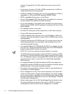
Figure 1-1. Computer Orientation . . . . . . . . . . . . . . . . . . . . . . . . . . . . . . 1-3
Figure 1-2. Front-Panel Features . . . . . . . . . . . . . . . . . . . . . . . . . . . . . . . 1-4
Figure 1-3. Back-Panel Features . . . . . . . . . . . . . . . . . . . . . . . . . . . . . . . 1-4
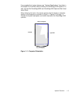
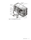
Figure 1-4. Back/Right Side Internal View . . . . . . . . . . . . . . . . . . . . . . . . 1-5
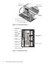
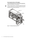
Figure 1-5. Opening the System Board Tray . . . . . . . . . . . . . . . . . . . . . . 1-6
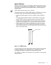
Figure 1-6. DIMM Sockets . . . . . . . . . . . . . . . . . . . . . . . . . . . . . . . . . . . 1-7
Figure 1-7. Power-Supply Paralleling Board. . . . . . . . . . . . . . . . . . . . . . 1-11
Figure 1-8. PSPB Power Connector PWR1 . . . . . . . . . . . . . . . . . . . . . . 1-12
Figure 1-9. PSPB Power Connector PWR2 . . . . . . . . . . . . . . . . . . . . . . 1-13
Figure 1-10. PSPB Power Connector PWR3 . . . . . . . . . . . . . . . . . . . . . . 1-13
Figure 1-11. PSPB Power Connector FD. . . . . . . . . . . . . . . . . . . . . . . . . 1-13
Figure 1-12. PSPB Power Connector HD_B/P. . . . . . . . . . . . . . . . . . . . . 1-14
Figure 1-13. System Board Components . . . . . . . . . . . . . . . . . . . . . . . . 1-15
Figure 1-14. SCSI Backplane Board. . . . . . . . . . . . . . . . . . . . . . . . . . . . . 1-16
Figure 1-15. System Board Jumpers. . . . . . . . . . . . . . . . . . . . . . . . . . . . 1-17
Figure 3-1. Hard-Disk Drive Indicators. . . . . . . . . . . . . . . . . . . . . . . . . . 3-17
Figure 4-1. Computer Cover Removal. . . . . . . . . . . . . . . . . . . . . . . . . . . 4-3
Figure 4-2. Front Bezel Removal . . . . . . . . . . . . . . . . . . . . . . . . . . . . . . . 4-4
Figure 4-3. Control-Panel Assembly Removal . . . . . . . . . . . . . . . . . . . . . 4-5
Figure 4-4. Drive Hardware . . . . . . . . . . . . . . . . . . . . . . . . . . . . . . . . . . . 4-6
Figure 4-5. Front-Panel Inserts . . . . . . . . . . . . . . . . . . . . . . . . . . . . . . . . 4-7
Figure 4-6. Externally Accessible Drive Removal . . . . . . . . . . . . . . . . . . 4-9
Figure 4-7. Drive-Mounting Rail Removal (Example). . . . . . . . . . . . . . . 4-10
Figure 4-8. Hard-Disk Drives in External Bay. . . . . . . . . . . . . . . . . . . . . 4-11
Figure 4-9. Hard-Disk Drive Removal . . . . . . . . . . . . . . . . . . . . . . . . . . 4-12
Figure 4-10. SCSI Backplane Board Removal . . . . . . . . . . . . . . . . . . . . . 4-14
Figure 4-11. Power Supply Removal . . . . . . . . . . . . . . . . . . . . . . . . . . . . 4-16
Figure 4-12. Power Cable Connections — Single Power Supply . . . . . . 4-17
Figure 4-13. PSPB Tray Location in the System Chassis . . . . . . . . . . . . 4-18
Figure 4-14. PSPB Installation on the PSPB Tray . . . . . . . . . . . . . . . . . . 4-19
Figure 4-15. Power Cable Connections — Multiple Power Supplies . . . 4-20
Figure 4-16. Power-Supply Paralleling Board Removal . . . . . . . . . . . . . . 4-21
Figure 4-17. System Cooling Fans. . . . . . . . . . . . . . . . . . . . . . . . . . . . . . 4-22
Figure 4-18. Three-Fan Assembly Removal. . . . . . . . . . . . . . . . . . . . . . . 4-23
Figure 4-19. Drive Fan Removal . . . . . . . . . . . . . . . . . . . . . . . . . . . . . . . 4-24
Figure 4-20. System-Board Fan Removal . . . . . . . . . . . . . . . . . . . . . . . . 4-25