


1-12 Dell PowerEdge 4300 Systems Service Manual
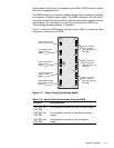
3LQ$VVLJQPHQWVIRUWKH363%3RZHU&RQQHFWRUV
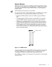
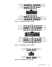
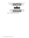
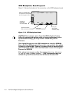
The power-supply output voltages can be measured at the back (wire side) of
the connectors without being disconnected. In the following diagrams, volt-
ages for the PSPB PWR
x
connectors are shown as measured at the system
board; voltages for the PSPB FD connector are shown as measured at the
PSPB; voltages for the PSPB HD_B/P connector are shown as measured at the
SCSI backplane.
1
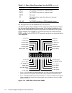
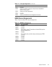
Pin 13 — SYS_PS_ON# should measure between +4.75 and +5.25 VDC except when the
power button on the front panel is pressed, taking SYS_PS_ON# to its active-low state.
2
Pin 5 — SYS_PWR_GOOD should measure between +4.75 and +5.25 VDC when the power
supply is operating to indicate that all power-supply output voltages are within the ranges
specified in Table 1-1.
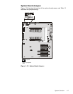
)LJXUH363%3RZHU&RQQHFWRU3:5
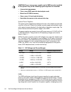
PWR1 To POWER1 connector on system board
PWR2 To POWER2 connector on system board
PWR3 Not used
FD To diskette drives and other devices in external
drive bays
HD_B/P To POWER connector on SCSI backplane board
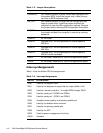
7DEOH3RZHU&DEOH&RQQHFWLRQV)URPWKH363%
FRQWLQXHG
&RQQHFWRU &DEOH&RQQHFWLRQ
13 14 15 16 17
common (black)
+5 VDC (red)
NC_TFSC (gray)
+5 VDC (red)
SYS_PS_ON #
1
(gray)
common (black)
common (black)
common (black)
–5 VDC (white)
+3.3 VDC (orange)
18
+5 VDC (red)
19 20 21 22 23 24
+5 VDC (red)
12345
+12 VDC (yellow)
+3.3 V_SENSE (orange)
common (black)
common (black)
+5 VFP (violet)
SYS_PWR_GOOD
2
(gray)
SENSE (black)
+5 V_SENSE (red)
common (black)
–12 VDC (blue)
6
+5 VDC (red)
789101112
+3.3 VDC (orange)