


System Overview 1-15
6\VWHP%RDUG/D\RXW
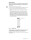
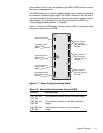
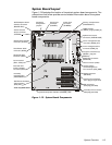
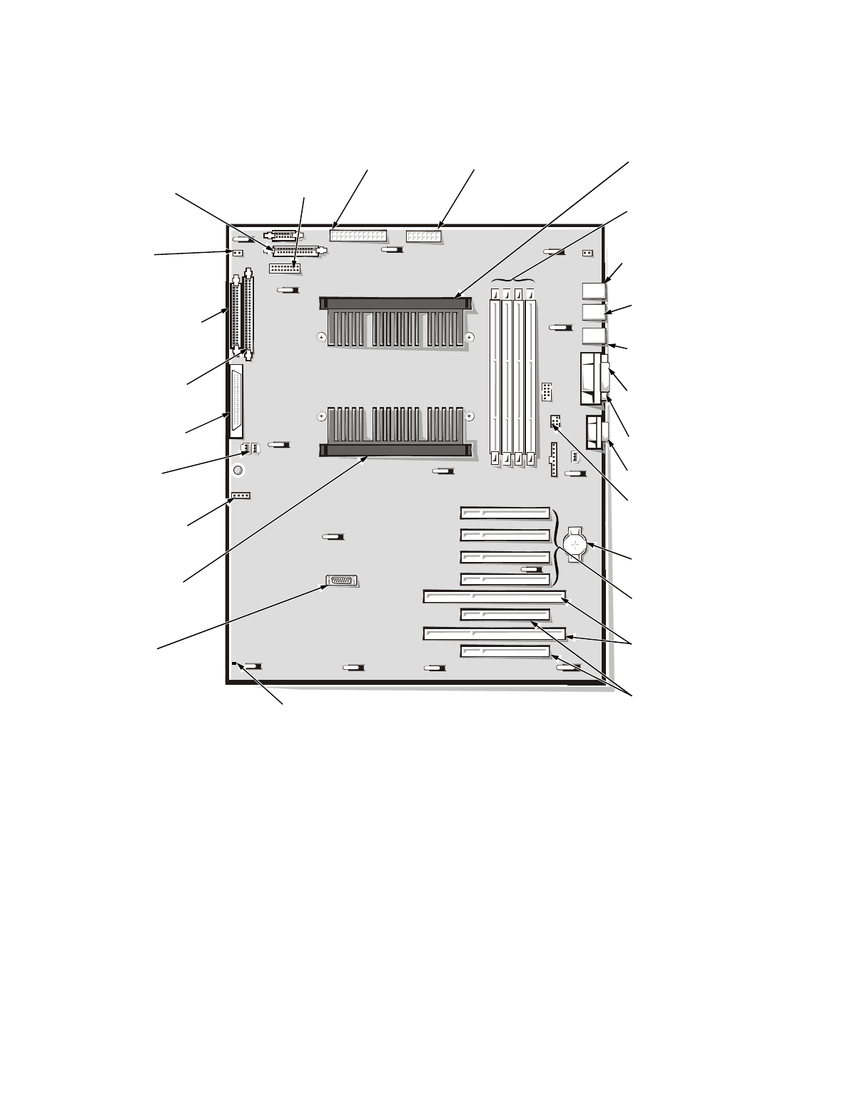
Figure 1-13 illustrates the location of important system board components. The
subsections that follow provide service-related information about the system
board components.
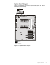
)LJXUH6\VWHP%RDUG&RPSRQHQWV
video connector (JVGA)
parallel port connector
(PARALLEL)
serial port connectors (2)
(SERIAL1 [top] and
SERIAL2)
keyboard and mouse
connectors (KYBD/MOUSE)
diskette-drive interface
connector (FLOPPY)
secondary
microprocessor
(PROCESSOR 2)
battery connector
(BATTERY)
Ultra/Narrow SCSI
connector (SCSI2)
DIMM sockets
(DIMM_A [right]–DIMM_D
)
speed and
configuration
jumpers
fan connectors
(FAN1, FAN2)
front of system board
primary microprocessor
(PROCESSOR 1)
ISA connectors
(ISA5 [top] and ISA6)
primary PCI connectors
(PCI1 [top] through PCI4)
power input
connector
(POWER1)
secondary PCI connectors
(PCI5 [top] and PCI6)
Ultra2/LVD SCSI
connector (SCSI1)
chassis-intrusion
switch connector
(INTRUS2)
SCSI backplane board
interface connector
(BACKPLANE)
server management bus
connector (XSMB_IN)
server management bus
connector (XSMB_OUT)
Dell Remote Assistant
Card connector
(SVR_MGT)
hard-disk drive
activity indicator
connector (HLED)
storage-system
server-management
bus connector (SDS_SMB)
power input
connector
(POWER2)
system-board power indicator (STANDBY_LED)