


Installing System Components 129
Installing a Processor
CAUTION: Many repairs may only be done by a certified service technician. You
should only perform troubleshooting and simple repairs as authorized in your
product documentation, or as directed by the online or telephone service and
support team. Damage due to servicing that is not authorized by Dell is not covered
by your warranty. Read and follow the safety instructions that came with the
product.
1
If you are adding a third and fourth processor for the first time, remove the
processor blank from the vacant processor sockets. Removing the blank is
similar to removing a processor. See "Removing a Processor" on page 125.
2
Remove the processor from the packing material by the processor’s edges
only. Do not touch the bottom of the processor. Handle the processor
carefully with your fingers on the side edges. Place your free hand beneath
the processor when you are moving it to the system to prevent dropping it
on the floor.
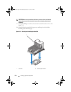
3
Locate the pin 1 indicator on the system board socket.
4
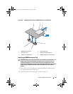
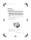
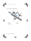
Locate the pin 1 indicator on the top of the processor. The pin 1 indicator
is shown as a triangle on the top of the processor. See Figure 3-24.
CAUTION: Positioning the processor incorrectly can permanently damage the
system board or the processor. Be careful not to bend the pins in the socket.
5
Place the processor over the socket with each pin 1 aligned with the pin
guide on the processor socket. See Figure 3-24.
CAUTION: Do not use force to seat the processor. When the processor is
positioned correctly, it engages easily into the socket.
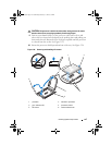
6 Align the notches in the
p
rocessor with the
socket keys on t
he ZIF
socket. See
Figure 3-24.
7
I
nstall the processor in the socket. Keep the processor in level (see
Figure 3-24
) and insert it straight down into the socket.
Allow the
processor to float on the pins, allowing the processor shield to hold it in
place.
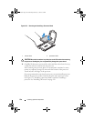
8
Verify that the processor is properly aligned and seated.
9
Close the processor shield. See Figure 3-24.
book.book Page 129 Wednesday, February 17, 2010 6:17 PM