


Installing System Components 147
Installing the System Board Assembly
1
Unpack the new system board assembly. If the I/O board was not removed
go to step 5.
2
Grasp the I/O board by its edge and the release pin and lower it into
the chassis.
3
Position the I/O board to the bottom of the chassis until it lays
completely flat.
4
Slide the I/O board toward the back of the system, inserting the connectors
into the cutouts on the chassis back panel.
5
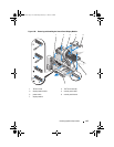
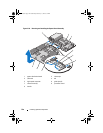
Holding by the handle and the board edge of the processor board
(see Figure 3-30), lower the processor board into the chassis. Lower the
processor board to the bottom of the chassis until it lays completely flat.
6
Rotate the levers outward 90 degrees and slide the processor board
backward so that the guide pins on one half of the high-speed connector
engages with the slots on the other half of the connector. See Figure 3-30.
7
Push the release levers inward until they lock into position.
See Figure 3-30.
8
Replace the processors and heat sinks on the new processor board.
See "Installing a Processor" on page 129.
9
Replace the memory modules. See "Installing Memory Modules" on
page 97.
10
Replace the cable clamp. See Figure 3-10.
11
Replace the cooling fan assembly. See "Installing the Cooling Fan
Assembly" on page 104.
12
If applicable, replace the NIC hardware key on the I/O board. See "Internal
NIC Hardware Key" on page 105.
13
If applicable, replace the expansion card risers. See "Installing Expansion-
Card Riser 1" on page 113 and "Installing Expansion-Card Riser 2" on
page 114.
14
If applicable, replace all expansion cards and the integrated storage
controller card. See "Installing an Expansion Card" on page 108 and
"Installing the Integrated Storage Controller Card" on page 117.
15
Slide the front-chassis assembly back into the system. See "Front-Chassis
Assembly" on page 90.
book.book Page 147 Wednesday, February 17, 2010 6:17 PM