


About Your System 19
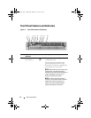
Item Indicator, Button, or
Connector
Icon Description
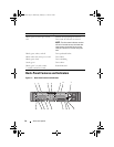
1 PCIe slot 1 PCI Express (Generation 2) x8 link
expansion slot (24.13 cm [9.5"] length).
2 PCIe slot 2 PCI Express (Generation 2) x4 link
expansion slot (low-profile 24.13 cm
[9.5"] maximum length, with a standard
height bracket).
3 PCIe slot 3 PCI Express (Generation 2) x8 link
expansion slot (low-profile 24.13 cm
[9.5"] length).
4 PCIe slot 4 PCI Express (Generation 2) x8 link
expansion slot (low-profile 24.13 cm
[9.5"] length).
5 PCIe slot 5 PCI Express (Generation 2) x8 link
expansion slot (24.13 cm [9.5"] length).
6 PCIe slot 6 PCI Express (Generation 2) x8 link
expansion slot (24.13 cm [9.5"] length).
7 Power supplies (2) 1100 W power supplies.
8 System identification
button
The identification buttons on the front
and back panels can be used to locate a
particular system within a rack. When
one of these buttons is pushed, the LCD
panel on the front and the system status
indicator on the back blink until one of
the buttons is pushed again.
9 System status
indicator
Lights blue during normal system
operation.
Lights amber when the system needs
attention due to a problem.
10 System identification
connector
Connects the optional system status
indicator assembly through the optional
cable management arm.
11 Ethernet connectors
(4)
Integrated 10/100/1000 NIC connectors.
book.book Page 19 Wednesday, February 17, 2010 6:17 PM