


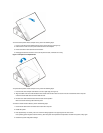
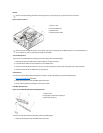
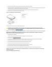
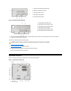
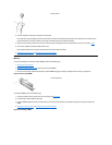

Figure 16. PCI/ISA Riser Board (Optional)
To remove the riser board, perform the following steps.
1. Remove the expansion-card cage.
2. Remove the expansion cards installed in the slots.
3. Remove the screws securing the riser board to the expansion-card cage.
4. Lift the riser board off the expansion-card cage.
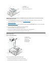
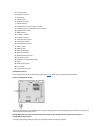
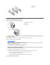
System Board Components
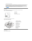
Figure 17 shows the system board and the location of all its sockets and connectors.
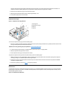
Figure 17. System Board Components
1
Auxiliary power indicator LED (AUX_LED)
2
Wakeup On LAN (WOL) connector
3
PCI expansion slot 1 (PCI1)
4
PCI expansion slot 2 (PCI2)
5
PCI expansion slot 3 (PCI3)
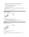
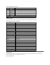
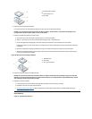
1
Auxiliary power LED (AUX_LED)
2
ISA expansion-card connector 1 (ISA1)
3
ISA expansion-card connector 2 (ISA2)
4
Remote Wakeup header (WOL)
5
PCI expansion-card connector 1 (PCI1)
6
PCI expansion-card connector 2 (PCI2)
NOTE: The ISA expansion-card connector 1 and PCI expansion-card connector 2 share an expansion slot; only one of these two
connectors can be used at any given time.
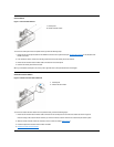
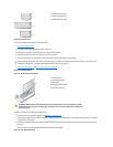
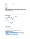
CAUTION: Ground yourself by touching an unpainted metal surface on the back of the computer.
1
Line-in connector