


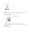
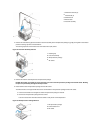

6. Lowerthepowersupplydownandawayfromthecomputer.
Expansion-Card Cage
To remove the expansion-card cage, perform the following steps:
1. Examine any cables connected to expansion cards through the back-panel openings and disconnect any cables that will not reach to where
the cage must be placed upon removal from the chassis.
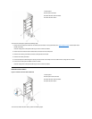
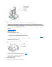
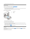
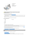
2. Locatethesecuringlever(seeFigure21). Rotate the lever upward until it stops in an upright position.
Figure 21. Expansion-Card Cage Removal
3. Slide the expansion-card cage out of the chassis.
4. Lift the expansion-card cage up and away from the chassis.
To replace the expansion-card cage, perform the following steps:
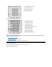
1. With the securing lever in the upright position, align the expansion-card cage tabs with the slots in the chassis opening for the expansion-
card cage (see Figure 21). Slide the expansion-card cage into place.
2. Rotate the securing lever downward, until it is flush with the top side of the chassis. Make sure that the riser board is fully seated in the RISER
connector on the system board (see Figure22).
3. Reconnect any cables you removed in step 1 of the previous procedure.
Riser Boards
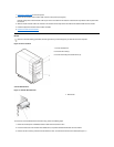
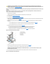
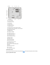
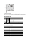
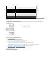
The mini tower chassis is available with either a PCI riser board (see Figure 22) or a PCI/ISA riser board (see Figure 23). The PCI riser board
provides five PCI expansion card slots. The PCI/ISA riser board provides three PCI expansion slots, two ISA expansion slots, and two shared
PCI/ISA expansion slots.
Figure 22. Mini Tower Chassis PCI Riser Board
NOTICE: Use a wrist grounding strap as explained in "Precautionary Measures."
1
Securing lever
2
Tabs (2)
3
Slots (2)