


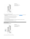
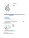
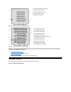
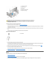

Figure 23. Mini Tower Chassis PCI/ISA Riser Board
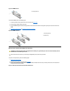
To remove a riser board, perform the following steps.
NOTICE: To avoid possibly damaging expansion cards or the system board by ESD, ground yourself by touching an unpainted
metal surface on the back of the computer.
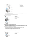
1. Remove the expansion-card cage.
2. Remove the expansion cards installed in the slots.
3. Remove the screws securing the riser board to the expansion-card cage.
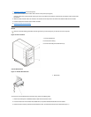
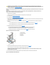
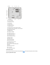
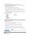
System Board Components
Figure 24 shows the system board and the location of all its sockets and connectors.
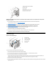
Figure 24. System Board Components
1
Auxiliary power indicator (AUX_LED)
2
PCI expansion slot 5 (PCI5)
3
Wake On LAN (WOL) connector
4
PCI expansion slot 1 (PCI1)
5
Auxiliary power connector
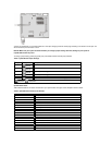
1
PCI expansion slot 1 (PCI1)
2
PCI expansion slot 2 (PCI2)
3
PCI expansion slot 3 (PCI3)
4
PCI expansion slot 4 (PCI4)
5
ISA expansion slot 1 (ISA1)
6
Standby power indicator LED (AUX_LED)
7
ISA expansion slot 4 (ISA4)
8
ISA expansion slot 3 (ISA3)
9
ISA expansion slot 2 (ISA2)
10
PCI expansion slot 5 (PCI5)
11
Remote Wakeup header (WOL)