


5. When the card is firmly seated in the connector, secure the card's mounting bracket to the chassis with the screw you removed in step 3.
6. Replace the expansion-card cage.
7. Connect any cables that should be attached to the card.
8. See the documentation for the card for information about the card's cable connections.
9. If you are installing the entry-level OptiPlex sound card, disconnect the internal speaker cable from the system board and reconnect it to the
INT SPKR connector on the sound card. You may have to route the speaker cable through a hole in the front of the chassis to reach the sound
card connector.
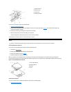
10. Replace the computer cover and reset the chassis intrusion detector.
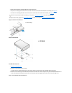
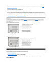
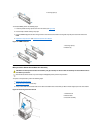
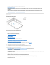
Riser Boards
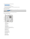
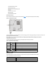
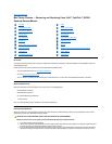
The midsize chassis is available with either a PCI riser board (see Figure 19) or a PCI/ISA riser board (see Figure 20). The PCI riser board
provides five PCI expansion card slots. The PCI/ISA riser board provides two PCI expansion slots, two ISA expansion slots, and one shared
PCI/ISA expansion slot.
Figure 19. Midsize Chassis PCI Riser Board
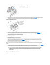
Figure 20. PCI/ISA Riser Board
Memory
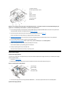
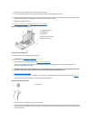
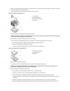
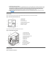
To remove a Rambus in-line memory module (RIMM), perform the following steps:
1. Remove the computer cover.
2. Rotate the system power supply to allow you to access the RIMMs.
3. Press the securing clips outward simultaneously until the RIMM disengages and pops out slightly from the socket (see Figure 21).
Figure 21. RIMM Removal
1
Standby power indicator (AUX_LED)
2
PCI expansion slot 5 (PCI5)
3
PCI expansion slot 4 (PCI4)
4
Remote Wakeup header (WOL)
5
PCI expansion slot 1 (PCI1)
6
PCI expansion slot 2 (PCI2)
7
PCI expansion slot 3 (PCI3)
1
Standby power indicator LED (AUX_LED)
2
ISA expansion slot 3 (ISA3)
3
ISA expansion slot 2 (ISA2)
4
ISA expansion slot 1 (ISA1)
5
Remote Wakeup header (WOL)
6
PCI expansion slot 1 (PCI1)
7
PCI expansion slot 2 (PCI2)
8
PCI expansion slot 3 (PCI3)