


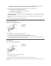
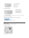
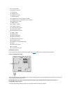
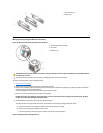

System Board Jumpers
Figure 18 shows the location of the jumpers on the system board. Table 1 lists the system board jumpers and their settings.
Figure 18. System Board Jumpers
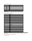
Jumpers are small blocks on a circuit board with two or more pins emerging from them. Plastic plugs containing a wire fit down over the pins. The
wire connects the pins and creates a circuit.
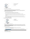
NOTICE: Make sure your system is turned off before you change a jumper setting. Otherwise, damage to your system or
unpredictable results may occur.
To change a jumper setting, pull the plug off its pin(s) and carefully fit it down onto the pin(s) indicated.
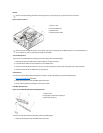
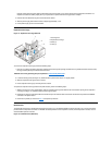
2
Line-out connector
3
Microphone connector
4
NIC connector
5
Video connector
6
Serial port 2 connector
7
USB connectors (2)
8
Keyboard (lower) and mouse (upper) connectors
9
Parallel port (upper) and serial port 1 (lower) connectors
10
Microprocessor connector
11
RIMM sockets (2)
12
DC power 1 connector
13
DC power 2 connector
14
Chassis intrusion connector
15
Control panel connector
16
External speaker connector
17
EIDE1 connector
18
EIDE2 connector
19
System board speaker
20
System board jumpers
21
Diskette/tape-drive connector
22
Riser board connector
23
Real-time clock reset (RTCRST) jumper
24
Battery
25
Modem audio connector
26
Fan connector
27
CD audio cable connector