


Back to Contents Page
Midsize Chassis — Removing and Replacing Parts: Dell™OptiPlex™GX200System
Service Manual
Overview
This section provides procedures for removing and replacing the components, assemblies, and subassemblies in the Dell OptiPlex 200 midsize
chassis system.
Unless otherwise noted, each procedure assumes that the following conditions exist:
l You have performed the steps in "Precautionary Measures."
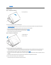
l You have removed the computer cover.
You can replace or reinstall a part by performing the removal procedure in reverse order unless additional information is provided.
Recommended Tools
The procedures in this file require the use of a #2 Phillips-head screwdriver.
Also, use a wrist grounding strap as explained in "Precautionary Measures."
Precautionary Measures
Before you perform any procedure in this section, take a few moments to read the following caution for your personal safety and to prevent
damage to the system from electrostatic discharge (ESD).
Overview
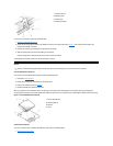
System Power Supply
Recommended Tools
System Board Components
Precautionary Measures
Expansion Cards
Computer Cover
Riser Boards
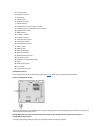
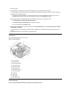
Internal View
Memory
Front-Panel Inserts
Microprocessor/Airflow Shroud/Heat Sink Assembly
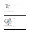
Expansion-Card Cage
System Battery
Control Panel
System Board
Drives
CAUTION: FOR YOUR PERSONAL SAFETY AND PROTECTION OF THE EQUIPMENT
Before you start to work on the system, perform the following steps in the sequence listed:
1. Turn off the computer and all peripherals.
2. Disconnect the computer and peripherals from their electrical outlets. Also, disconnect any telephone or telecommunication lines from
the computer. Doing so reduces the potential for personal injury or shock.
3. If you are disconnecting a peripheral from the computer or are removing a component from the system board, wait 10 to 20 seconds
after disconnecting the computer from the electrical outlet before disconnecting the peripheral or removing the component to avoid
possible damage to the system board.
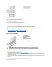
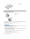
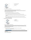
4. Wear a wrist grounding strap, and clip it to an unpainted metal surface, such as the padlock loop on the back of the chassis. If a wrist
grounding strap is not available, touch any unpainted metal surface on the back of the computer or on the computer chassis, such as
thepowersupply,todischargeanystaticchargefromyourbodybeforetouchinganythinginsidethecomputer.Whileyouwork,
periodically touch an unpainted metal surface on the computer chassis to dissipate any static electricity that might harm internal
components. Also avoid touching components or contacts on a card and avoid touching pins on a chip.
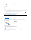
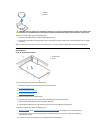
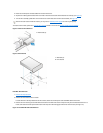
5. Verify that the standby power indicator
on the riser board is not on. If it is on, you may need to wait 10 to 30 seconds for it to go out (see