


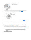
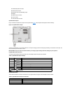

NOTICE: You must match the colored strip on the EIDE cable with pin 1 on the IDE1 connector to avoid possible damage to your
system. Pin 1 is indicated by a silk-screened "1" printed on the system board.
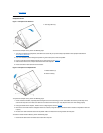
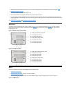
3. If it is not already connected, connect the other end of the EIDE cable to the appropriate EIDE interface connector on the system board.
To locate the IDE1 connector on the system board, see Figures 19 and 20.
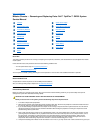
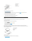
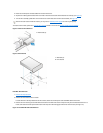
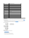
4. Connect a DC power cable into the power input connector on the back of the drive (see Figure 12).
Check all connectors to be certain that they are properly cabled and firmly seated.
5. Replace the computer cover. Then reconnect your computer and peripherals to their electrical outlets, and turn on the peripherals.
6. Insert a bootable diskette into drive A, and turn on the computer system.
7. Reset the chassis intrusion detector. While in System Setup, update the Drive 0 option under Primary Drive n.
8. Partition and logically format your drive before proceeding to the next step.
See the documentation for your operating system for instructions.
9. Install your operating system on your hard-disk drive.
Refer to the documentation that came with your operating system.
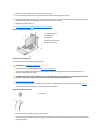
System Power Supply
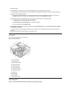
System Power Supply Rotation
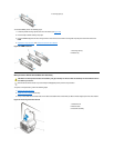
To access some components on the system board, you may have to rotate the system power supply out of the way. To rotate the power supply,
perform the following steps:
1. Remove the computer cover.
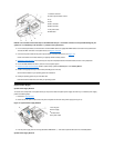
2. Disconnect the AC power cable from the AC power receptacle on the back of the power supply (see Figure 13).
Figure 13. System Power Supply Rotation
3. Free the power supply from the securing tab labeled "RELEASE—>, " and rotate it upward until it locks in its extended position.
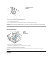
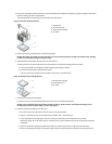
System Power Supply Removal
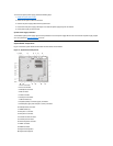
1
Interface connector
2
Power input connector on drive
3
Lip
4
Rail
5
IDE1 connector
6
IDE2 connector
7
DC power cable
8
EIDE cable
1
Securing tab
2
Power supply
3
Release latch
4
AC power cable