


7. Unpack the new microprocessor package.
If any of the pins on the new microprocessor appear to be bent, return the microprocessor package.
NOTICE: You must position the microprocessor package correctly in the ZIF socket to avoid permanent damage to the
microprocessor and the computer when you turn on the system.
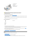
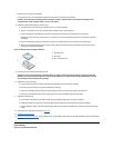
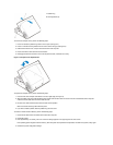
8. Install the microprocessor package in the ZIF socket.
a. If the release lever on the ZIF socket is not all the way out, move it to that position.
b. Align pin-1 (the beveled corner) of the microprocessor package and pin-1 of the ZIF socket.
c. Set the microprocessor package lightly in the socket, making sure that all the pins are headed into the correct holes.
Because the system uses a ZIF socket, there is no need to use force (which could bend the pins if the microprocessor package is
misaligned).
d. When the microprocessor package is positioned correctly, press it with minimal pressure to fully seat it in the ZIF socket.
e. When the microprocessor package is fully seated, pivot the release lever back toward the system board until it snaps into place,
securing the microprocessor package.
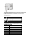
Figure 34. Microprocessor Package Installation
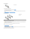
9. Unpack the heat sink included in the replacement kit.
NOTICE: Do not reuse the old heat sink assembly when you replace the microprocessor package. Using the old heat sink
assembly can cause the microprocessor to overheat because there is not enough thermal compound between the old heat
sink assembly and the microprocessor package.
10. Replace the heat sink assembly.
a. Peel the release liner from the adhesive tape attached to the bottom of the new heat sink assembly.
b. Place the heat sink assembly on top of the microprocessor package.
c. Orient the metal retaining clip and hook the unhinged end of the clip over the tab on the top edge of the ZIF socket.
d. Press down on the hinged end of the clip to snap the clip over the tab on the bottom edge of the ZIF socket.
11. Replace the airflow shroud.
a. Insert the two chassis hooks on the airflow shroud into the chassis tabs located above the system cooling fan.
b. Position the shroud at an angle to the chassis then rotate the shroud down over the microprocessor/heat sink assembly.
c. Squeeze both pairs of tabs on the sides of the shroud and lower it until the clips on the bottom of the shroud engage the top of the ZIF
socket.
12. Rotate the power supply back into place (see Figure 20).
13. Replace the computer cover.
14. Reset the chassis intrusion detector. While in System Setup, confirm that the system data area correctly identifies the type of microprocessor
installed.
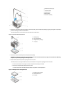
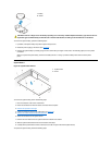
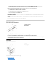
System Battery
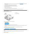
Figure 35. System Battery Removal
1
Microprocessor
2
ZIF socket
3
Pin-1 (beveled corner)