


DGS-3700-12/DGS-3700-12G Series Layer 2 Gigabit Ethernet Switch User Manual
10
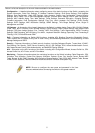
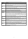
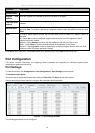
Parameter Description
Static
Allows the entry of an IP address, Subnet Mask, and a Default Gateway for the Switch. These
fields should be of the form xxx.xxx.xxx.xxx, where each xxx is a number (represented in decimal
form) between 0 and 255. This address should be a unique address on the network assigned for
use by the network administrator.
DHCP
The Switch will send out a DHCP broadcast request when it is powered up. The DHCP protocol
allows IP addresses, network masks, and default gateways to be assigned by a DHCP server. If
this option is set, the Switch will first look for a DHCP server to provide it with this information
before using the default or previously entered settings.
BOOTP
The Switch will send out a BOOTP broadcast request when it is powered up. The BOOTP
protocol allows IP addresses, network masks, and default gateways to be assigned by a central
BOOTP server. If this option is set, the Switch will first look for a BOOTP server to provide it with
this information before using the default or previously entered settings.
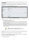
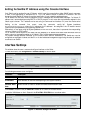
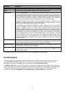
IP Interface
This field displays the IP Interface that is currently being used on the Switch.
Management
VLAN Name
This allows the entry of a VLAN Name from which a management station will be allowed to
manage the Switch using TCP/IP (in-band via web manager or Telnet). Management stations that
are on VLANs other than the one entered here will not be able to manage the Switch in-band
unless their IP addresses are entered in the Security IP Management window. If VLANs have
not yet been configured for the Switch, the default VLAN contains all of the Switch's ports. There
are no entries in the Security IP Management table, by default, so any management station that
can connect to the Switch can access the Switch until a management VLAN is specified or
Management Station IP Addresses are assigned.
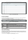
Interface Admin
State
This field enables or disables the Interface Admin State. When the state is enabled, the IPv4
processing will be started when the IPv4 address is configured on the IPIF. The IPv6 processing
will be started when the IPv6 address is explicitly configured on the IPIF.
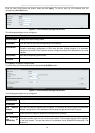
IPv4 Address
The address should specify a host address and length of the network prefix. There can be
multiple IPv4 addresses defined on an interface. Thus, as a new address is defined, it is added on
this IP Interface.
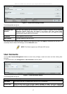
Subnet Mask
A Bitmask that determines the extent of the subnet that the Switch is on. Should be of the form
xxx.xxx.xxx.xxx, where each xxx is a number (represented in decimal) between 0 and 255. The
value should be 255.0.0.0 for a Class A network, 255.255.0.0 for a Class B network, and
255.255.255.0 for a Class C network, but custom subnet masks are allowed.
Gateway
IP address that determines where packets with a destination address outside the current subnet
should be sent. This is usually the address of a router or a host acting as an IP gateway. If your
network is not part of an Intranet, or you do not want the Switch to be accessible outside your
local network, you can leave this field unchanged.
Click Apply to implement changes made.