


5-74 APPLICATION FUNCTIONS
MON2000
GC Serial Port and Cable Configurations JULY 2010
5.18 GC SERIAL PORT AND CABLE
CONFIGURATIONS
This section provides more detailed
information about the serial port connections of
the 2350A GC Controller. It identifies serial
port pin assignments and diagrams for
designing RS-232 serial cables necessary for
your application.
GC serial ports are found on the GC Controller
Terminal Board for field wiring, and the
connection points for external devices are as
follows:
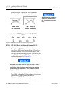
External modem connections can be made to
any of the four serial ports. However, a possible
exception exists for Serial Port 4: the internal
modem for the Model 500 with the 2350A
Controller, if installed, uses Serial Port 4.
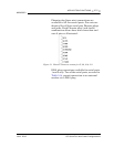
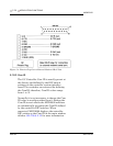
Table 5-14 Serial Ports on GC Terminal Board
Port DB-9 Plug Phoenix Plug
1 (COM1) P2 J5
2 (COM2) P3 J6
3 (COM3) n/a J10
4 (COM4) n/a J11
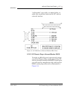
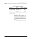
The Mode column applies only to the following
CPU boards:
• 2350A CPU board (P/N 2-3-2350-190)
• Model 700 CPU board (P/N 2-3-0700-036)