


INSTALLATION AND SETUP 2-49
MON2000
JULY 2010 BASIC 2350A CONFIGURATION
2.14 BASIC 2350A CONFIGURATION
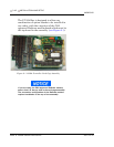
At this point, install, if any, all mounting
hardware and optional PC/104 boards onto the
2350A CPU Board.
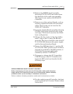
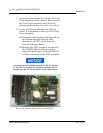
1. Install the 2350A CPU (P/N 3-2350-090)
into slot 3 of the card cage assembly.
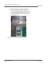
2. Install cables on the CPU Board in the
following sequence:
(a) Digital I/O cable (P/N 3-2350-081) from
CPU J7 to the System Interface Board
J2.
(b) Digital I/O cable (P/N 3-2350-080) from
CPU J4 to the System Interface Board
J3.
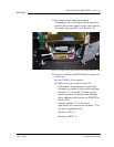
(c) COM1, COM2, and the printer cable (P/
N 3-2350-083) from CPU J1 to the
System Interface Board J4, J9, and J11.
(d) COM3 and COM4 can be configured two
different ways. To configure a system
WITHOUT a keyboard and display,
connect cable (P/N 3-2350-084) from
CPU J6 to the System Interface Board
J8 and J10. This provides access to
COM3 on J10 and COM4 on J11 of the
Field Termination board. The serial port
setup in the MON2000 Software for
COM4 must be selected as a PC port.
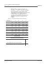
(e) For a system WITH a keyboard and
display, connect cable (P/N 3-2350-087)
from CPU J6 to the System Interface J8
and J12. This provides access to COM3
on J10 and COM4 is dedicated for use as
a serial interface to the keyboard and
display. COM4 will not be available at
J11 of the Field Termination board.