


2-44 INSTALLATION AND SETUP
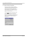
MON2000
Conversion Process JULY 2010
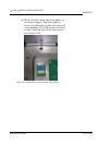
4. Lower the TB down and out of the way, held
in place by its ground straps at the bottom
of the board. This exposes the Card Cage
Assembly.
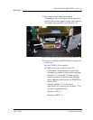
5. Loosen the four screws that secure the Card
Cage Assembly to the chassis. Then remove
the Card Cage Assembly away from its
chassis mount so that it is easy to work on.
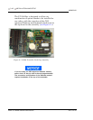
6. Locate the System Interface and Driver
board. It is mounted to the top of the Card
Cage Assembly.
7. Remove all cables connected to the System
Interface Board (P/N 3-2350-005,
P/N 3-2350-022, or P/N 3-2350-023).
8. Remove the I/O48 Board assembly (drawing
P/N BE-12973) and cables from the top slot
of the Cage Card Assembly. This board is
not used on the 2350A GC Controller.
9. Remove the CPU Board assembly (P/N CE-
19281) and cables from the second slot of
the card cage assembly. This board is not
used on the 2350A GC Controller.