


3-20 Chapter 3
DCP386i/486e Daughterboard Cabling
This section discusses cable connections between the 8-port daughterboard
on the DCP386i and DCP486e adapters and external devices.
RS-232 Cabling
The serial ports on the 8-port daughterboard are connected to external
devices via an 8-port breakout cable. Each port provides a standard 25-pin
male RS-232C connector for attachment to external devices.
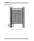
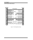
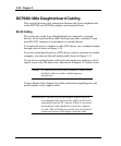
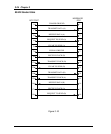
To connect the port to a modem or other DCE device, use a standard straight-
through cable as shown in Figure 3-10.
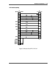
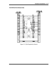
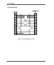
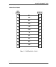
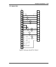
If you are connecting the port to a DTE device, such as a terminal or another
computer, you must use the null-modem cable shown in Figure 3-11.
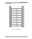
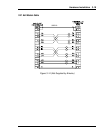
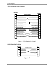
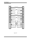
If your device and application software do not require any modem or clock
signals (async only) the three-wire cable shown in Figure 3-15 may be used.
NOTE: All connections to the board should be made using
shielded cables to reduce radio frequency
interference.
Contact Emulex Sales Support for further information regarding price and
model number of any support cables.
IMPORTANT: In order to provide proper strain relief it is
recommended that the breakout cable not be freely
suspended from the PC chassis. If this is necessary,
the breakout cable should be secured to a chassis
or rack. This will help prevent the loss of electrical
connection between the adapter and the cable.