


X.25 Configuration 7-5
Diagramming Your X.25 Network
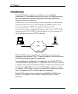
To ensure that all connections to the X.25 network are properly diagrammed,
complete these step:
1) Diagram the existing X.25 network showing all router access points and
mark the X.25 addresses.
2) Draw each type of connection from the local router to its corresponding
partner.
For PVC-type connections, show the LCN assigned by the X.25 network
service provider and the partner name.
For SVC-type connections, list the partner names.
Planning Your X.25 Network
To ensure that all aspects of your planned connections to the X.25 network
are covered, complete the following steps:
For each location that a router attaches to the X.25 network, specify the
following parameters:
− Physical interface required (for example, V.35 or RS-232)
− Internal interface speed required (for example, 9600 or 19200)
This value is needed only when the clocking is generated internally;
otherwise, clocking comes from the modem.
Number of partner routers which will be connected using X.25 and
whether a PVC or an SVC is required for each.
− Packet size required (for example, 128 bytes or 256 bytes)
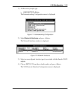
Emulex X.25 Router ID (at top of page) - Symbolic name assigned by
the system administrator to identify a particular Emulex X.25 router. The
ID provides a way to track or reference a particular Emulex X.25 router.
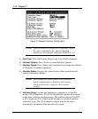
Frame Level Parameters
Sequencing Modulo - Specifies the numbering of sequential frames
allowed in a Data-Link layer window. Modulo 8 is specified for 1984
CCITT X.25 Specifications.
Window Size (k) - Determines the maximum number of
unacknowledged frames that can be received or sent before requiring an
acknowledgment by the remote destination.