


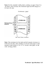
Interface Specifications
Your printer is equipped with an 8-bit parallel interface. For
specifications on optional interfaces, refer to their manuals.
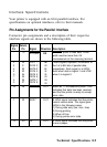
Pin Assignments for the Parallel Interface
Connector pin assignments and a description of their respective
interface signals are shown in the following table.
Signal Return
Pin
Pin
Signal Direction Description
1
19
STROBE IN
STROBE pulse to read data. Pulse
width must be more than 0.5
microseconds at the receiving terminal.
2
20
DATA 1
IN
These signals represent information of
3
21
DATA 2
IN
the 1st to 8th bits of parallel data,
4
22
DATA 3 IN
respectively. Each signal is at HIGH
5 23 DATA 4
IN
level when data is logical 1 and LOW
6
24 DATA 5
IN
when it is logical 0.
7 25
DATA 6
IN
8
26
DATA 7 IN
9
27 DATA 8
IN
10 28
ACKNLG
OUT About an 11-microsecond pulse. LOW
indicates that data has been received
and that the printer is ready to accept
more data.
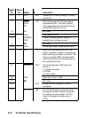
11
29
BUSY
OUT A HIGH signal indicates that the printer
cannot receive data. The signal goes
HIGH in the following cases:
1) During data entry (ea. char. time)
2) During printing
3) When off line
12
30 PE
OUT
4) During printer-error state
A HIGH signal indicates that the printer
is out of paper.
Technical Specifications 8-9