


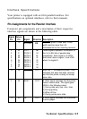
Signal
Pin
13
Return
Pin
-
Signal
SLCT
OUT
14
-
-
-
Auto
FEED
-
XT
15
16
17
NC
Direction
IN
-
GND
-
-
CHASSIS
-
GND
-
-
18
-
19-30
-
31
16
NC
-
GND
-
INIT
IN
32
-
ERROR
OUT
33
34
35
-
GND
-
-
NC
-
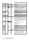
Not used.
- -
OUT
36
-
SLCT IN
IN
Description
Pulled up to +5 volts through 3.3 Kohm
resistance.
When this signal is LOW, the paper is
automatically fed 1 line after printing.
(The signal level can be fixed to this by
setting DIP switch 2-4 to on.)
Not used.
Logic ground level.
Printer’s chassis ground, which is
isolated from the logic ground.
Not used.
Twisted-pair return signal ground level.
When this level becomes LOW, the
printer controller is reset to its power-up
state and the print buffer is cleared. This
level is normally HIGH; its pulse width
must be more than 50 microseconds at
the receiving terminal.
This level becomes LOW when the
printer is:
1) in paper out state.
2) off line.
3) in error state.
Same as for Pins 1 Q-30.
Pulled up to 5V through 3.3 Kohm
resistance.
The DC1/DC3 code is valid only when
this signal is HIGH. (Internal fixing can
be carried out with Jumper J10. The
level of this signal is factory-set to
LOW.)
8-10
Technical Specifications