


FPC Installation and Operation, cont’d
FPC 5000 Front Panel Controller • FPC Installation and Operation2-4
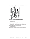
5. Repeat step 4 for each of the remaining three mounting blocks.
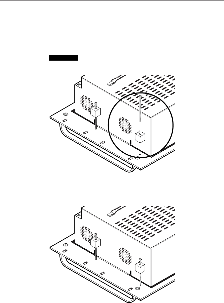
6. Thread one of the included 60 mm panhead machine screws into the top of
each mounting block. Repeat for the other screws.
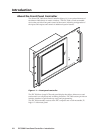
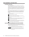
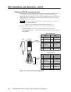
7. Tighten the screws until they just contact the rack-mounting panel. Move the
panel as necessary to ensure that the four screws contact the panel in the inset
holes (figure 2-3).
CAUTION
Do not overtighten the screws. The screws may bend if overtightened. If
you are using a torque screwdriver, set the screwdriver to release at a
minimal amount of torque.
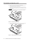
Figure 2-3 — Inserting the machine screws
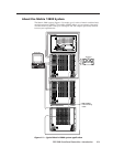
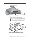
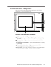
8. Lift the FPC computer and tighten each screw until the panel is firmly flush
against the back side of the FPC computer’s LCD panel (figure 2-4).
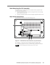
Figure 2-4 — Fully assembled Front Panel Controller