


2-9FPC 5000 Front Panel Controller • FPC Installation and Operation
Front Panel Features and Operation
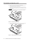
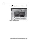
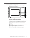
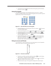
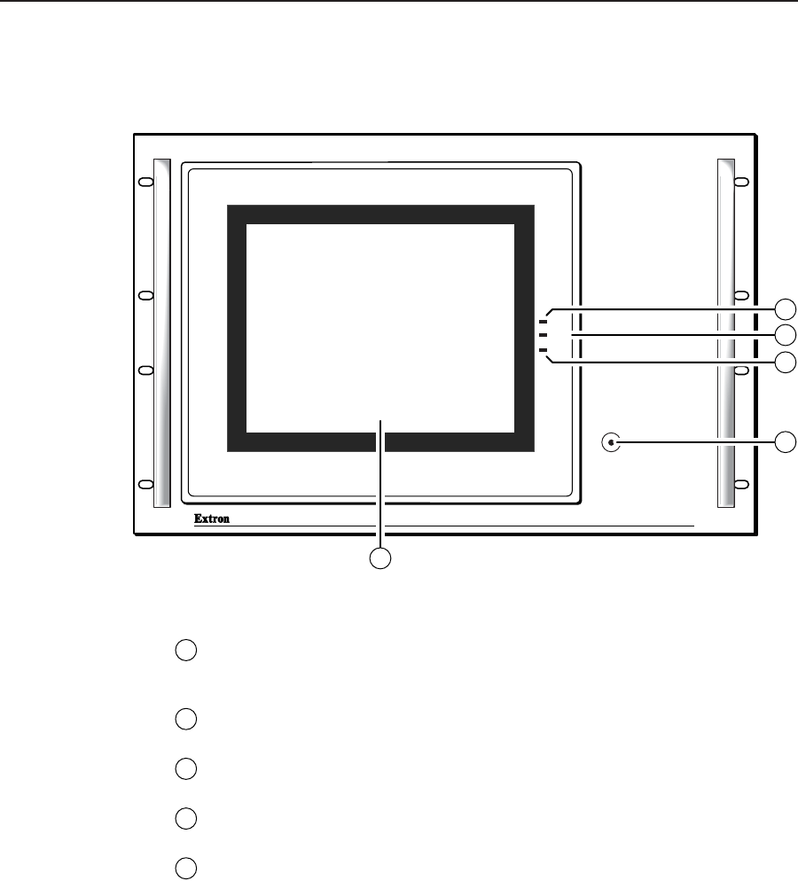
Other than the power switch, the remaining control and all of the FPC 5000
indicators are on the front panel (figure 2-10).
MATRIX SWICHER CONTROLLER
PWR
HDD
T/R
RESET
FPC 5000
2
4
3
5
1
Figure 2-10 — Front panel control and indicators
1
LCD touch panel — The LCD panel displays front panel controller screens.
The touch panel responds to selections that the operator makes by touching
the screen.
2
Power indicator — Lights to indicate power is connected and the FPC is
turned on.
3
H(ard) D(isk) D(rive) indicator — Lights to indicate that the FPC is accessing
its hard disk.
4
T(ransmit)/R(eceive) indicator — Lights to indicate that the FPC is
transmitting or receiving data on the Net port.
5
Reset button — Use a small screwdriver or tweeker to press the Reset button
if the FPC computer hangs up. This button reboots the computer.