


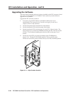

FPC Installation and Operation, cont’d
FPC 5000 Front Panel Controller • FPC Installation and Operation2-6
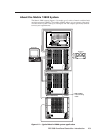
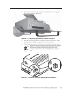
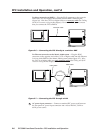
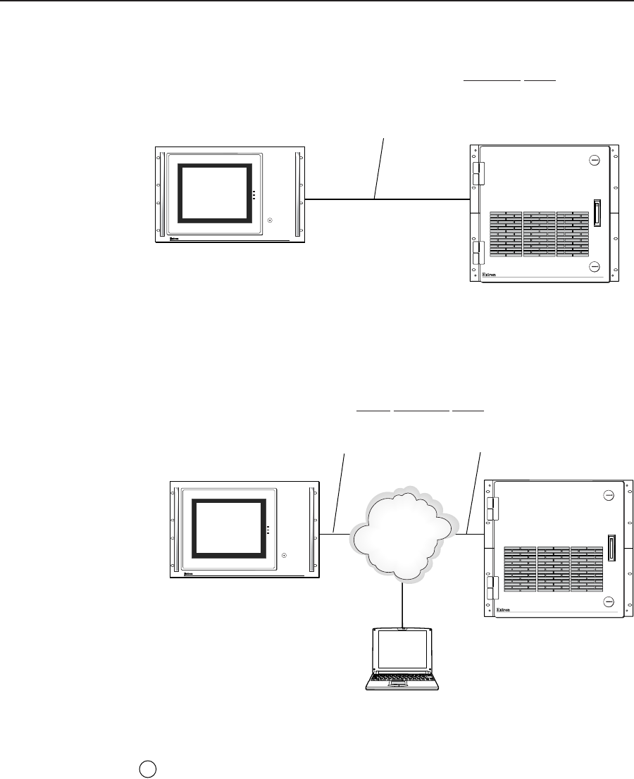
For direct connection to BME 0 — Plug the RJ-45 connector on the opposite
end of the CAT 5e or higher cable directly into the BME 0 Ethernet port
(figure 2-6). Wire the CAT 5e or higher cable as a
crossover cable (See Cabling
and RJ-45 connector wiring in this chapter). For a multi-BME system, ensure
that you connect the FPC to BME 0.
MATRIX SWICHER CONTROLLER
PWR
HDD
T/R
RESET
FPC 5000
FPC 5000
Matrix 12800
Crossover Cable
MATRIX 12800
WIDEBAND VIDEO
Figure 2-6 — Connecting the FPC directly to a switcher BME
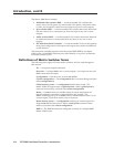
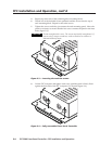
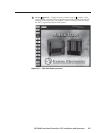
For Ethernet connection to the Matrix 12800 system — Plug the RJ-45
connector on the opposite end of the CAT 5e or higher cable into the Ethernet
LAN on which BME 0 of the Matrix 12800 system resides (figure 2-7). Wire
the CAT 5e or higher cable as a
patch (straight) cable (See Cabling and RJ-45
connector wiring in this chapter).
MATRIX SWICHER CONTROLLER
PWR
HDD
T/R
RESET
FPC 5000
Ethernet
FPC 5000
Matrix 12800
Laptop
Patch Cable
Patch Cable
MATRIX 12800
WIDEBAND VIDEO
Figure 2-7 — Connecting the FPC through a LAN
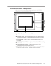
2
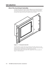
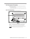
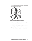
AC power input connector — Connect a standard IEC power cord between
the rear panel AC power input connector and a 100 to 240VAC, 50 Hz or
60 Hz power source.