


FPC Installation and Operation, cont’d
FPC 5000 Front Panel Controller • FPC Installation and Operation2-8
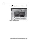
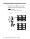
Cabling and RJ-45 connector wiring
It is vital that your cable between the FPC 5000 and the Matrix 12800 BME 0 or
LAN be the correct cable, and that it be properly terminated with the correct
pinout. This FPC link requires CAT 5e or CAT 6, unshielded twisted pair (UTP) or
shielded twisted pair (STP) cables, terminated with RJ-45 connectors. The cable
length is limited to 328’ (100 m).
Do not use standard telephone cables. Telephone cables will not support the
FPC-Matrix 12800 link.
Do not stretch or bend cables. Transmission errors can occur.
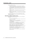
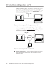
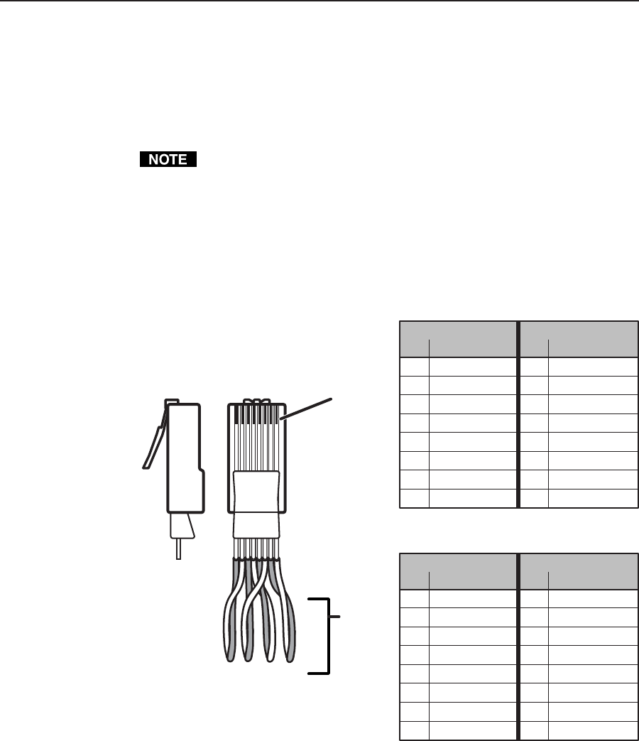
The cable must be properly terminated for your application (figure 2-9):
• Crossover cable — Direct connection between the FPC and BME 0.
• Patch (straight) cable — Connection of the FPC to an Ethernet LAN that also
hosts BME 0.
Clip DownSide
1
1&2
3&6 4&5
7&8
2345678
1Pins 2345678
RJ-45
connector
Patch (straight) cable
Twisted
Pairs
Side 1 Side 2
Pin Wire color Pin Wire color
1 White-orange 1 White-orange
2 Orange 2 Orange
3 White-green 3 White-green
4 Blue 4 Blue
5 White-blue 5 White-blue
6 Green 6 Green
7 White-brown 7 White-brown
8 Brown 8 Brown
Crossover cable
Side 1 Side 2
Pin Wire color Pin Wire color
1 White-orange 1 White-green
2 Orange 2 Green
3 White-green 3 White-orange
4 Blue 4 Blue
5 White-blue 5 White-blue
6 Green 6 Orange
7 White-brown 7 White-brown
8 Brown 8 Brown
Figure 2-9 — RJ-45 connector pinout tables