


Installation
This section describes the installation and the operation of the MPS602, including:
• Mounting the Switcher
• Rear Panel Connections
• Twisted Pair Recommendations
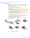
• LockIt Lacing Bracket
• Cabling the MPS602 Switcher
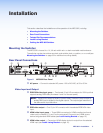
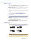
Mounting the Switcher
The MPS602 is housed in a 1U, full rack widthrack- or desk-mountable metal enclosure.
The switchercan also be surface-mounted under a table, desk, or podium, or on a wall (see
Mounting the Switcher on page33 for additionalmounting details).
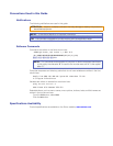
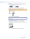
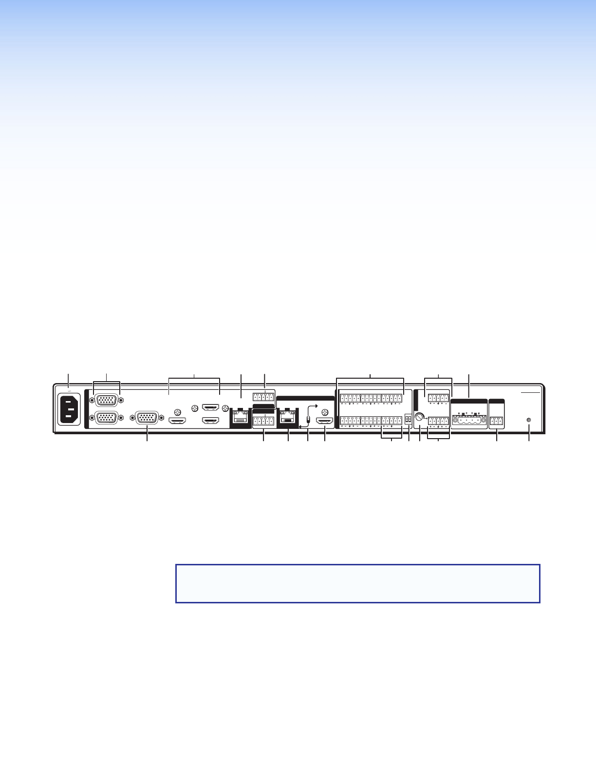
Rear Panel Connections
L
R
SIG LINK
DTP IN
SIG LINK
DTP OUT
50/60 Hz
100-240V 1.0A MAX
1
2
RGB OUT
HDMI
MIC
MIX
RS-232
MPS 602 SA
Tx Rx G
MUTE HDMI AUDIO
PHANTOM POWER
SELECT
3
4
5
6
OUTPUTS
AMP OUT REMOTE
OVER DTP
OVER DTP
RS-232 IR
Rx GTx Tx Rx
RS-232 IR
Rx GTx Tx Rx
CLASS 2 WIRING
8Ω / 4Ω
INPUTS
AUDIO IN
AUDIO OUT
L 1 R L 2 R L 3 R
L VARIABLE R
L FIXED R
L 4 R L 5 R MIC LINE
R
k
n
op s
ab
c
dg
hij
fq
elmr
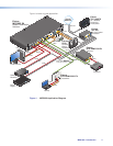
Figure 2. MPS602 Rear Panel
a AC power — Connect to standard AC power: 100 to 240 VAC, at 50 or 60 Hz.
Video Input and Output
b RGB/VGA video input group — Two female 15-pin HD connectors for VGA input that
supports analog RGB video (numbered 1 and 2 on the rear panel).
NOTE: The MPS602 does not scale or convert video, however it does convert an
analog RBG input to digital for the digital outputs. The output signal resolution is
the same as the input resolution.
c RGB video output — One 15-pin HD connector with the selected RGB/VGA video
input.
d HDMI video input group — Three HDMI connectors for HDMI compliant audio and
video input (numbered 3, 4, and 5 on the rear panel). Connect to any HDMI source
device using standard HDMI cables (see LockIt Lacing Bracket on page10).
e HDMI video output — Connect an HDMI display device for output from the selected
HDMI input (see LockIt Lacing Bracket on page10).
MPS602 • Installation 5