


UL Rack Mounting Guidelines
The following Underwriters Laboratories (UL) guidelines pertain to the safe installation of the
MPS602 in a rack.
1. Elevated operating ambient temperature — If installed in a closed ormulti-unit rack
assembly, the operating ambient temperature of the rack environmentmay be greater
than room ambient temperature. Therefore, install the device in an environment
compatible with themaximum ambient temperature (Tma = +122 °F, +50 °C) specified
by Extron.
2. Reduced air flow — Install the equipment in a rack so that the amount of air flow
required for safe operation of the equipment is not compromised.
3. Mechanical loading — Mount the equipment in the rack so that a hazardous condition is
not achieved due to unevenmechanical loading.
4. Circuit overloading — Connect the equipment to the supply circuit and consider the
effect that circuit overloadingmight have on overcurrent protection and supply wiring.
Appropriate consideration of equipment nameplate ratings should be used when
addressing this concern.
5. Reliable earthing (grounding) — Maintain reliable grounding of rack-mounted equipment.
Pay particular attention to supply connections other than direct connections to the
branch circuit (e.g. use of power strips).
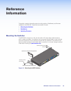
RackMounting
Rackmount the switcher as follows:
1. Attach the supplied rackmounting brackets to the switcher with the eight provided
#8machine screws, (see figure 19 on page 33).
2. Insert the switcher into the rack, aligning the holes in themounting bracket with those of
the rack.
3. Secure the switcher to the rack using the suppliedmachine screws.
Table or WallMounting
The table/wallmounting brackets extend approximately 1/4 inch (6.4mm) above the top
surface of the switcher enclosure allowing for an air space between the enclosure and the
surface. Table or wallmount the switcher as follows:
1. Attach the table/wallmounting brackets to the switcher with the eight provided
#8machine screws (see figure 19).
2. Hold the switcher with the attached brackets against the underside of the table or other
furniture, or against the wall. Mark the location of the screw holes of the bracket on
themounting surface.
3. Drill 3/32 inch (2mm) diameter pilot holes, 1/4 inch (6.4mm) deep in themounting
surface at themarked screw locations.
4. Insert #8 wood screws into the four pilot holes. Tighten each screw into themounting
surface until just less than 1/4 inch of the screw’s head protrudes.
5. Align themounting screws with the slots in the brackets and place the switcher against
the surface, with the screws through the bracket slots.
6. Slide the switcher slightly forward or back, then tighten all four screws to secure the
switcher in place.
MPS602 • Reference Information 34