


Remote
Communication and
Control
This section discusses SIS programming and control of the MPS602 including:
• Connection Options
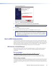
• Host-to-MPS Communications
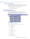
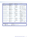
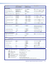
• Command and Response Table
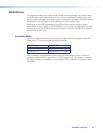
Connection Options
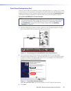
The MPS602 can be remotely connected via a host computer or other device (such as a
control system) attached to the rear panel RS-232 port or the front panel USB Config port.
The switcher can be set up and controlled using Simple Instruction Set (SIS) commands.
SIS commandsare executed using the Extron DataViewer program, found at
www.extron.com.
Remote Control Port (RS-232)
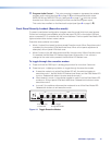
The RS-232 port connector (see figure 2,
r
on page 5) connects to a host or external
controlling device, such as a computer or control system, which can generate the proper
command codes and recognize switcher responses.
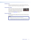
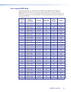
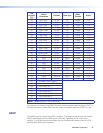
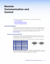
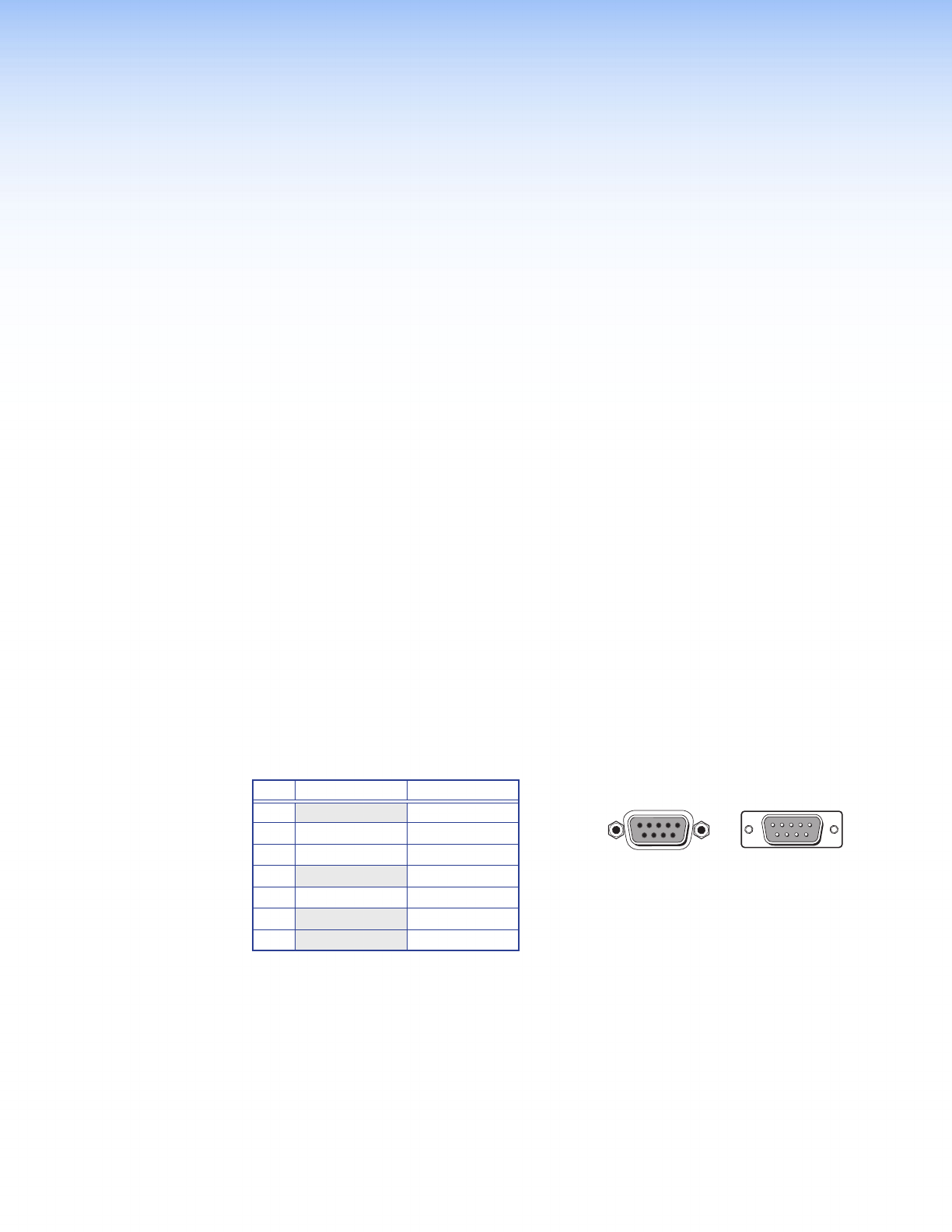
The RS-232 connector on the PC is a 9-pin D female with the following pin designations:
Pin RS-232 Function Description
1 - No connection
2 Tx Transmit data
3 Rx Receive data
4 - No connection
5 Gnd Signal ground
6,7 - No connection
8,9 - No connection
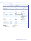
The protocol for the serial port is as follows: 9600 baud, no parity, 8 data bits, 1 stop bit, no
flow control. Commands and responses for programming the MPS602 from a host system
connected to the RS -232 or USB port are listed later in this chapter.
51
9
5
9
6
1
6
Female Male
MPS602 • Remote Communication and Control 22