


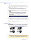
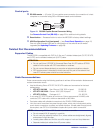
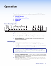
l Mic/Line input — One 3-pole captive screw connector switchable betweenmic
and line level inputs. Wire the connector as shown below (see figure 4). Use the
configuration software to select themic or line input level.
"
(5 mm) MAX. (typ)
3
16
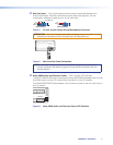
Audio INPUT Wiring
Balanced Input
Sleev
e
Ring
Tip
Tip
Sleeve
Jumper
Unbalanced Input
Figure 4. 3.5mm, 3-pole Captive ScrewMicrophone Connector
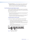
ATTENTION: Do not tin thewire leads before installing into the connector. Tinned
wires are not as secure in the connector and could be pulled out.
MUTE HDMI AUDIO
PHANTOM POWER
AUDIO IN
L 3 R
MIC LINE
L
3
R
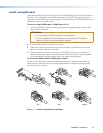
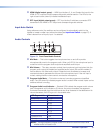
Figure 5. Mic/Line Rear Panel Connection
NOTE: Although the rear mic/line input is 5-pole, only 3 poles are used by the
mic/line connector. Be certain to plug the 3-pole mic/line connector into the
correct position.
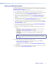
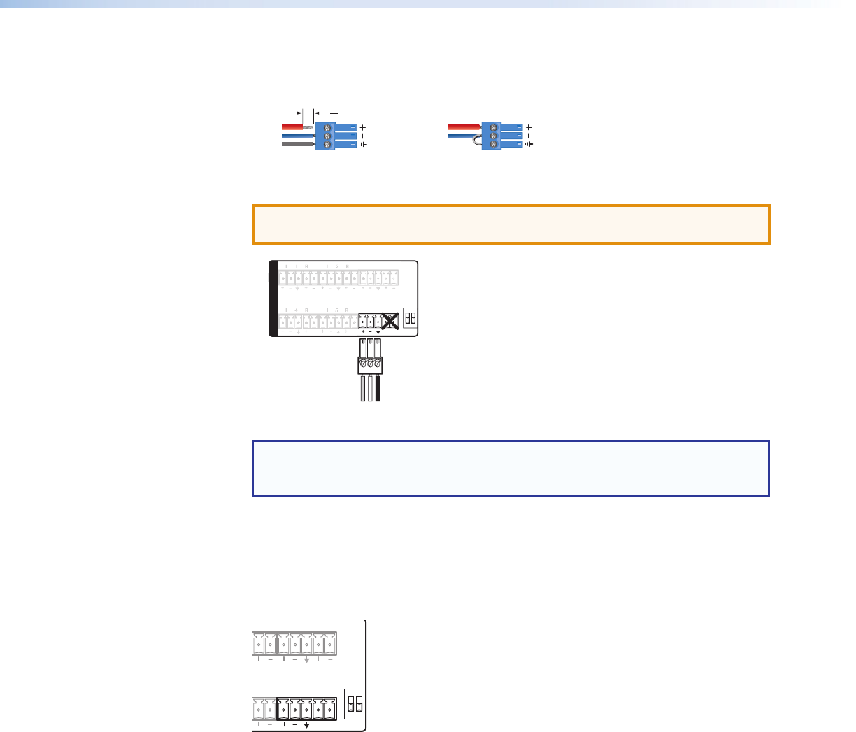
m Mute HDMI Audio and Phantom Power— Two 2-position DIP switches.
The MUTE HDMI AUDIO switch (see figure 6) mutes the HDMI embedded audio on both
the HDMI output and the DTP output when the switch is in the UP position.
The PHANTOM POWER switch selects +48V phantom power for themic input when in
the UP position.
MUTE HDMI AUDIO
PHANTOM POWER
AUDIO IN
L 1 R L 2
R L 3 R
L 4 R L 5
R MIC LINE
Figure 6. Mute HDMI Audio and Phantom Power DIP Switches
MPS602 • Installation 7