


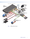
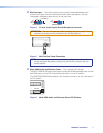
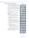

Cabling the MPS602 Switcher
The MPS switcher can be connected to asmany as six input devices. It can output to one
of two outputs (HDMI or DTP). Follow the steps below and the installation example (see the
MPS 602 Application Diagram on page11)
1. Turn off power to the MPS switcher and all devices that will be connected to it.
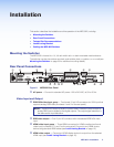
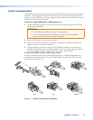
2. If the MPS switcher is rack, table/wall, or through-deskmounted, position the brackets
and install themounting screws (see Mounting the Switcher on page33).
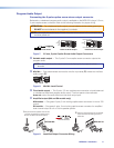
3. Attach up to two analog, three HDMI (or DVI-D with appropriate adapters) sources,
and one DTP transmitter device to the switcher (see Rear Panel Connections on
page5).
4. Connect the switcher HDMI output to a compatible display device, or the DTP output to
a compatible DTP receiver (see Rear Panel Connections on page5).
5. For stereo audio input, connect up to six audio sources to the corresponding audio
inputs of the analog (1 and 2), HDMI (3 through 5), or DTP (6) video groups (see Rear
Panel Connections on page5).
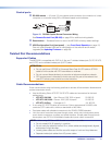
6. For vocal input, connect a mic to the Mic/line input (see Rear Panel Connections on
page5). Set the phantom power switch if necessary.
7. For output, connect an appropriate audio output device depending on the switcher
model:
• All models – Connect an audio amplifier to the program or fixed Audio Output
connectors (see Rear Panel Connections on page5).
• MPS602SA – Connect stereo speakers to the speaker output connections.
• MPS602MA – Connect a 70V line speaker system to the speaker output
connections.
NOTE: The program and fixed outputs are on all models. On models with
internal amplifiers the outputs are used exactly as they are on non-amplified
models.
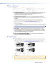
8. Connect a control PC or controller to the switcher using:
• The rear panel RS-232 port and a 3-pole captive screw connector (
k
) (see
Remote Control Port (RS-232) on page22).
• The front panel USB configuration port (see Front Panel Configuration Port on
page23).
9. Power up the input and output devices, then connect power to the rear AC connector
of the switcher (see Rear Panel Connections on page5).
MPS602 • Installation 11