


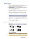
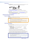
Program Audio Output
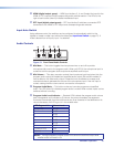
Connecting the 5-pole captive screw stereo output connector
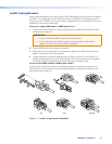
Balanced or unbalanced program audio output is available on the MPS602 using a 3.5mm,
5-pole captive screw connector. Refer to the following illustration for proper wiring.
ATTENTION: For unbalanced audio output, connect sleeves to the center ground pin.
DO NOT connect sleeves to the negative (–) contacts.
NOTE: Do not tin the audio leads. Tinned wires are not as secure in the connector and
could be pulled out.
Do not tin the wires!
Balanced Audio Output
Tip
Ring
Tip
Ring
Sleeves
Unbalanced A
udio Output
Tip
No Ground Here
No Ground Here
Tip
Sleeves
LR
LR
Figure 7. 3.5mm, 5-pole Captive Screw Audio Output Connectors
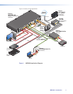
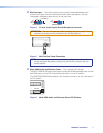
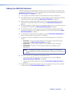
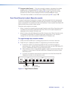
n Variable audio output — This 5-pole 3.5mm captive screw connector outputs the
program audio.
NOTE: The variable audio output level is controlled by the front panel volume
encoder.
o Mic Mix — One potentiometer controls the mic/line input level (
l
) mixed into the fixed
audio output (
p
).
L
R
SIG LINK
DTP IN
SIG LINK
DTP OUT
50/60 Hz
100-240V 1.0A MAX
1
2
RGB OUT
HDMI
MIC
MIX
RS-232
MPS 602 SA
Tx Rx G
MUTE HDMI AUDIO
PHANTOM POWER
SELECT
3
4
5
6
OUTPUTS
AMP OUT REMOTE
OVER DTP
OVER DTP
RS-232 IR
Rx GTx Tx Rx
RS-232 IR
Rx GTx Tx Rx
CLASS 2 WIRING
8Ω / 4Ω
INPUTS
AUDIO IN
AUDIO OUT
L 1 R L 2 R L 3 R
L VARIABLE R
L FIXED R
L 4 R L 5 R
MIC LINE
R
k
n
op s
ab
c
dg
hij
fq
elmr
Figure 8. Mic Mix Level Control
p Fixed audio output — This 5-pole, 3.5mm captive screw connector outputs balanced
or unbalanced fixed level program audio output. The front panel volume encoder
doesnot control the audio level from this audio output port.
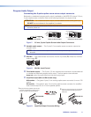
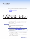
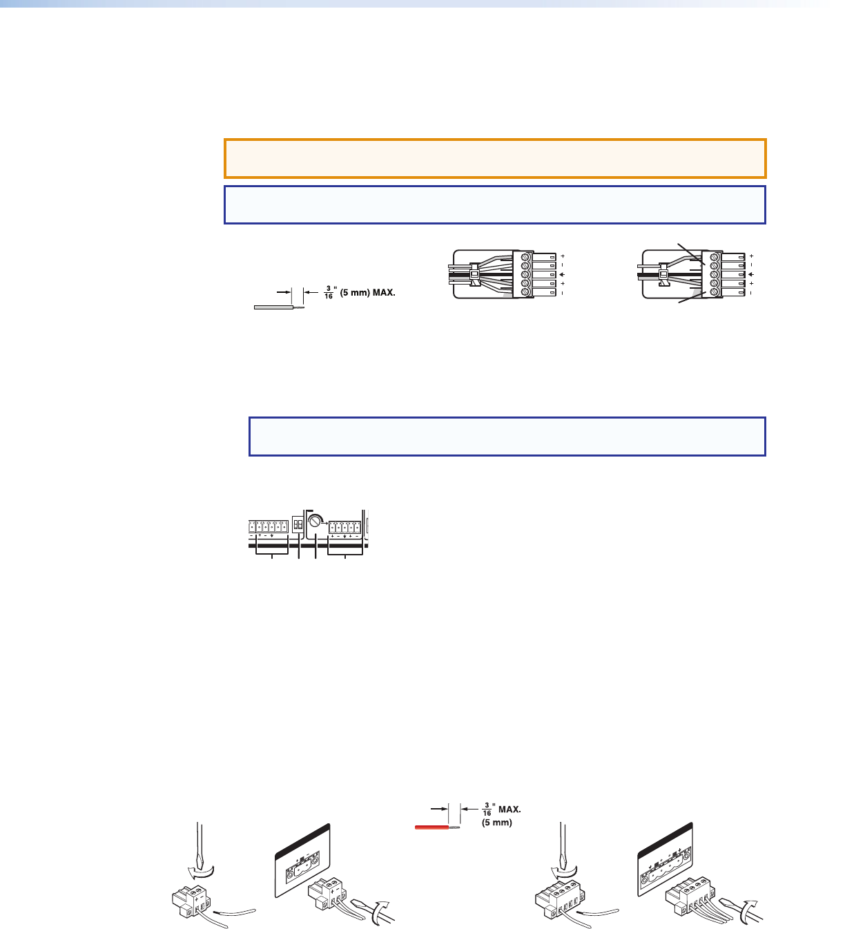
q Amplified output (MA and SA models only)
MA models — One green 2-pole, 5mm locking captive screw connector for mono 70V
output.
SA models — One green 4-pole, 5mm locking captive screw connector for amplified
dual channel output to a 4 or 8 ohm speaker system.
AMP OUT
CLASS 2 WIRING
70V
L
R
AMP OUT
CLASS 2 WIRING
8Ω / 4Ω
21
MPS 602 MA MPS 602 SA
21
1 Strip and insert the speaker wires into the
connector and tighten the captive screws.
Be sure to observe the correct polarit
y.
2 Insert the wired connector into the amplifier
output and secure the locking screws on
either side.
Do not tin the wires!
Figure 9. Amplified Output Connector Wiring
MPS602 • Installation 8