


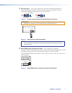
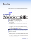
DTP Input and Output
f DTP In — Connect a DTP 230 source (Tx) to this RJ-45 jack (numbered 6 on the rear
panel). The DTP input includes the HDMI (or DVI with the proper adapter) video with
embedded audio, bi-directional RS-232 and IR, separate balanced or unbalanced
analog audio, and remote power for a connected DTP Tx device.
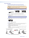
g RS-232 and IR Over DTP In — One 3.5mm 5-pole captive screw connector provides
connection for bidirectional RS-232 and remote IR signals between the DTPTx
connected to input 6 (figure 2,
f
) of the MPS602.
h RS-232 and IR Over DTP Out — One 3.5mm 5-pole captive screw connector to
connect and pass bi-directional RS-232 and IR between the MPS602 and DTP230Rx.
RS-232
To pass bidirectional serial command signals between DTP-compatible devices,
connect a control device to the three leftmost poles (Tx, Rx, and G) of the 5-pole
captive screw connector (see Twisted Pair Recommendations on page9).
IR Over DTP Wiring
To transmit and receive IR signals, connect a control device to the two rightmost poles.
NOTE: RS-232 and IR data can be transmitted or received simultaneously.
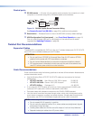
i DTP output — Connect an Extron DTP 230 device using this RJ-45 jack. The DTP
230 signal format and protocol is used. The output can include HDMI (with embedded
audio), bidirectional RS-232 and IR, separate analog audio (from the fixed audio output),
and remote power for a connected DTP230 receiver.
j DTP out or HDMI out selection switch — One single-pole double-throw switch to
select either the DTP (
i
) or HDMI (
e
) output.
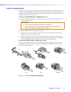
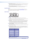
Analog Audio Input
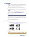
k Audio input group —Five 3.5mm, 5-pole captive screw connectors provide analog
audio input to the switcher. Inputs 1-5 accept either balanced or unbalanced audio. The
audio level of each analog audio input is adjusted using the configuration software or
using the front panel (see Audio Gain and Attenuation Adjustments on page17).
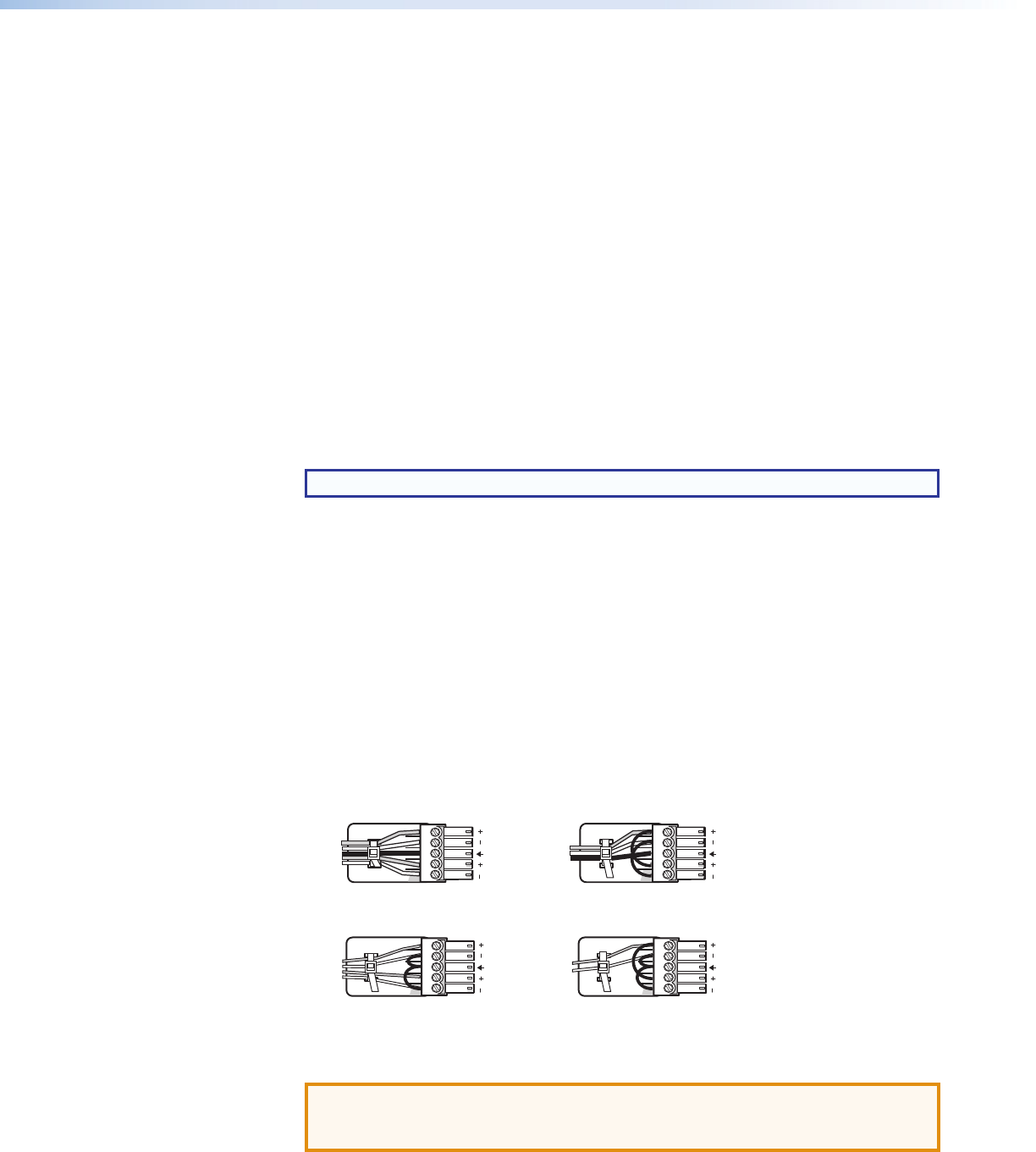
Unbalanced Stereo Input
Balanced Stereo Input
Tip
Ring
Tip
Ring
Slee
ves
Do not tin the wires!
Tip
Sleeve
Sleeve
Tip
Unbalanced Mono Input
Balanced Mono Input
(high impedance)
Tip
Ring
Sleeve
Tip
Sleeve
Audio Input
LR
LR
LR
LR
Figure 3. Audio Input Wiring
ATTENTION: The audio input group input numbers correspond to the associated
video inputs. Audio inputs 1 and 2 are associated with RGB video inputs 1 and
2. Audio inputs 3, 4, and 5 are associated with HDMI video inputs 3, 4, and 5.
MPS602 • Installation 6