


2-3
PoleVault Systems Installation • Installation — Stage 1
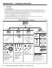
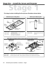
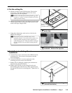
1. Mark screen location
a. Mark the center line and the outer edges of screen.
T
When marking the location of screens, devices, or site
for installing transmitters and MediaLink control
devices, use painters’ tape to avoid wall surface damage.
When marking the center line of the screen,
where possible, keep it aligned with the center of the
ceiling tile. This makes the projector installation and
alignment easier.
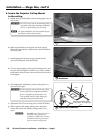
b. Mark any structural studs, utility pipes, conduits,
or fire-breaks before drilling the hardware holes.
Do not drill the holes at this time.
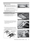
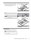
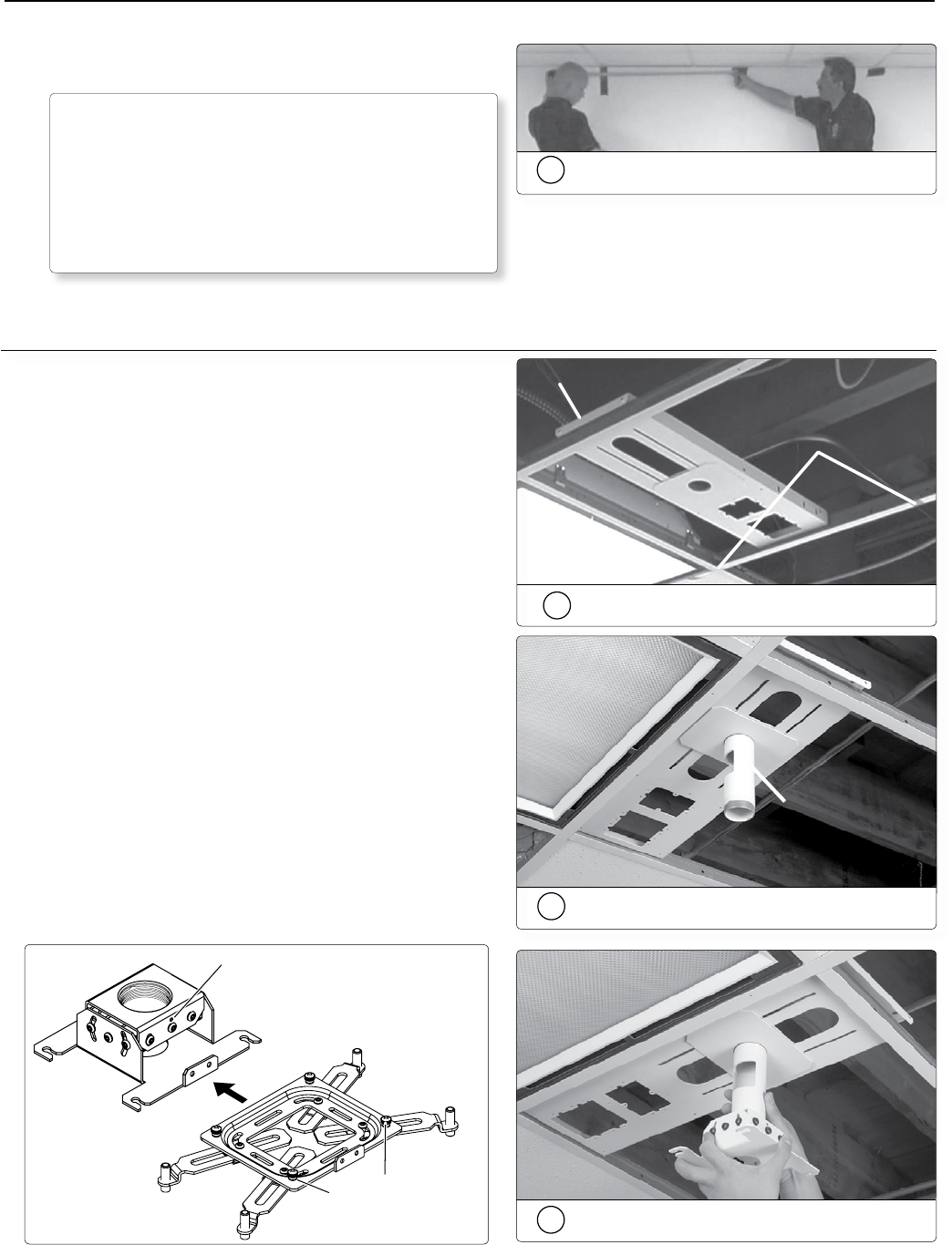
2. Install projector to verify location
a. Remove the ceiling tiles, and mark the maximum and
minimum throw distances on the T-frame.
b. Place the PCM 240 over the T-frame, between the two
marks. Lightly tighten the frame screws.
c. Back out the set screws on the PCM 240 adapter plate
and screw the PMP into the pipe adapter, with the cable
access hole closest to the ceiling. Turn it so the cable
access hole faces away from the screen.
Tighten the set screws.
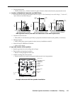
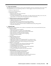
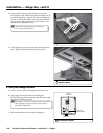
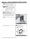
d. Back out the set screws on the top portion (the adjuster
plate, see
a
below) of the UPB 25, and screw the plate
onto the base of the PMP. Align it so the security flange
is at the rear. Tighten the set screw.
Adjuster Plate
Locking Screws (4)
Projector
Bracket
Adjuster
Plate
Loosen the four Adjuster Plate
Locking Screws and slide the
Adjuster Plate away from the
Projector Bracket
a
b
Set Screws (2)
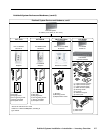
Minimum/Maximum
Throw Distance Marks
PCM
2b
Place the PCM 240 on the T-bar
1a
Mark the screen location
PMP installed
onto PCM 240
2c
Install the PMP
2d
Screw the adjuster plate onto the PMP