


PoleVault Systems Installation • Optional Accessory Installation
2-30
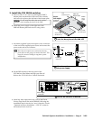
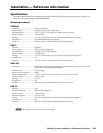
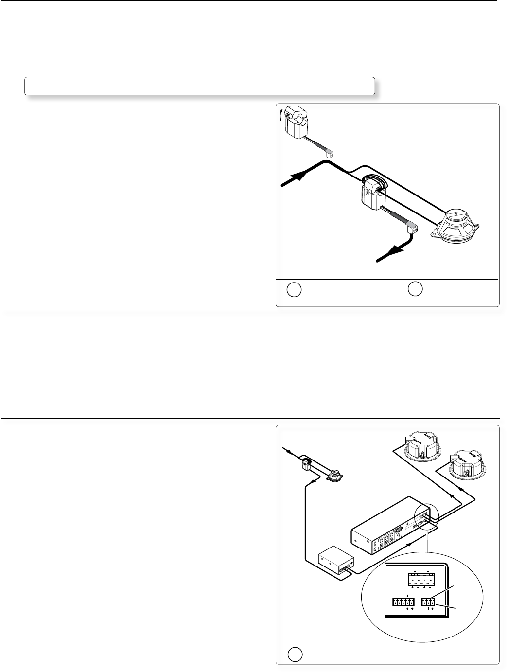
Optional Accessory Installation — PPC 25
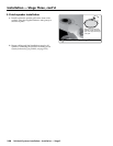
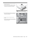
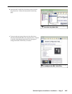
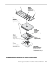
1. Connect sensor to paging speaker
a. Open the top of the Priority Page Sensor.
b. Loop (only) one of the Paging speaker wire leads around
the top (open) part of the Sensor. Either speaker wire
will work. Leave the other speaker wire connected
directly to the Paging speaker. Polarity need not be
observed.
• For a 25 V or 70V system — wrap 5 to 8 loops.
• For a 4/8 ohm system — wrap 2 to 4 loops.
c. Close the top of the Priority Page Sensor.
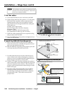
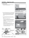
2. Connect sensor to the PPC 25
a. Cut an 18" section from the unterminated end of the
supplied blue sensor cable, for use in step 3.
b. Connect the bare wire end of the supplied blue sensor
cable to the 2-pole captive screw connector on the Page
Sensor. Polarity need not be observed.
c. Route the connector end of the sensor cable to the PPC 25
Controller and plug it into the Paging Sensor port.
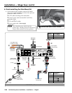
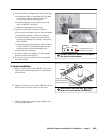
3. Connect the PPC 25 to the switcher
a. Connect the 18" cable made in step 2a to the Relay Out
port on the PPC 25 Controller and to the mute and
ground pins on the PVS 204SA Vol/Mute port. Polarity
need not be observed.
b. Use the included power supply cable assembly
(PN 27-576-01LF) to power the PPC 25 from the
PVS 204SA power supply. The PPC 25 must be mounted
near the PVS 204SA and its power supply.
Open the
Sensor
Ceiling Mounted
Paging Speaker
Page
Sensor
From
PA system
To Priority
Page Controller
1a
Open the sensor and
1b
Loop wire
around the sensor
P
O
W
E
R
CN
O
P
A
G
IN
G
R
E
L
A
Y
D
E
L
A
Y
S
E
N
S
IT
IV
IT
Y
1
2
V
0
.2
A
M
A
X
O
N
1
2
L
R
A
UX
/M
IX IN
D
O
N
O
T
G
R
O
U
N
D
O
R
S
H
O
R
T
S
P
E
A
K
E
R
O
U
T
P
U
T
S
!
1B
1A
I
N
P
U
T
S
O
U
T
P
U
T
S
2B
2A
3B
3A
RS-232
M
L
C/IR
DC
VO
L
4/8 O
hm
s
AM
PLIFIED OUTPUTS
V
OL
/M
UTE
Tx
ABC
RxIR12V
10V
POW
ER
1
2
V
3
A
M
A
X
U
S
L
I
S
T
E
D
17T
T
AUDIO/VID
EO
APPARATUS
®
R
G
B
V
ID
E
O R
G
B
V
ID
E
O
Ceiling Mounted
Paging Speaker
Page
Sensor
From Classroom
Paging System
Relay
Output
Remote
Vol/Mute
Control
Extron
PPC 25
Priority Page
Controller
Extron
PVS 204SA
Twisted Pair
Switcher
LR
RS-232 MLC/IR
DC VOL
4/8
Ohms
AMPLIFIED OUTPUTS
VOL/MUTE
Tx
ABC
RxIR 12V
10V
Mute
(center)
PVS 204SA
rear panel
Ground
(right)
PV SI 3C LP
Ceiling
Speakers
P
l
e
n
u
m
R
a
t
e
d
U
L
2
0
4
3
S
u
i
t
a
b
l
e
f
o
r
U
s
e
i
n
A
ir
-
H
a
n
d
l
in
g
S
p
a
c
e
s
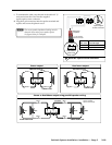
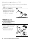
The example below is the installation of the optional accessory Priority Page Controller and Sensor (PPC 25).
The Priority Page Controller momentarily silences classroom audio whenever a page is made from a public address
(PA) system.
For detailed information, refer to the PPC 25 Installation Instructions, supplied with the device.
N
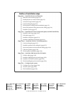
Follow all local fire and safety code requirements for installation and anchoring.
3a
Connect the relay to the switcher