


PoleVault Systems Installation • Installation — Stage 2
2-14
Installation — Stage Two, cont’d
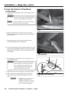
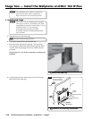
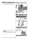
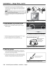
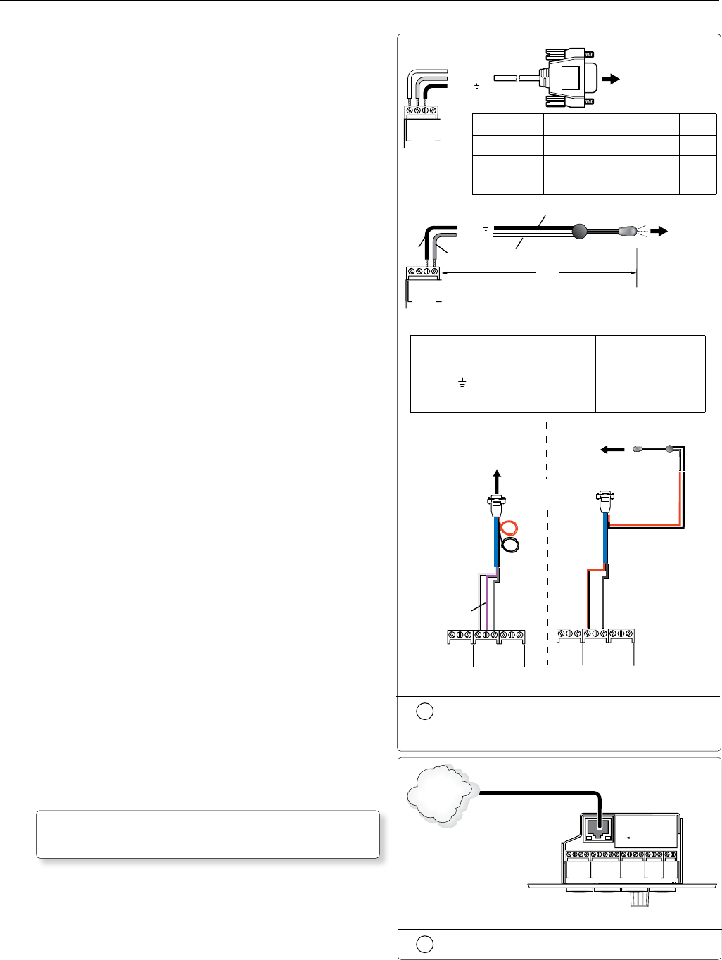
b. Connect the IR/RS-232 projector communication cable as
shown for either RS-232 or IR projector control.
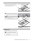
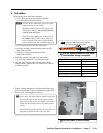
c. Connect a CAT 5, 5e, or 6 straight through cable to the
MLC ‘s RJ-45 jack.
W
DO NOT connect the MLC’s RJ-45 jack
to the PVS 204SA twisted pair inputs.
4b
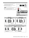
Connect the MLC to the projector with
an RS-232 cable or IR emitter cable, as
appropriate.
1
2
3
GROUND
+12 V OUT
CM
GROUND
IR OUT
GROUND
SCP
GROUND
Tx
Rx
DISPLAY
RS-232/IR
A B C D E
COMM LINK
LAN
PRESS TAB WITH
TWEEKER TO REMOVE
A B
MLS
RS-232
POWER
12V
DIGITAL
I/O
IR IN
Tx
GROUND
Rx
+12 V IN
MLC 104 IP Plus Right Side Panel
TCP/IP
Network
CAT 5 Cable
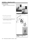
4c
Connect to the LAN using a CAT 5 cable
MLC 104 IP Plus
Right Side Panel
Ground ( )
Receive (Rx)
Tr ansmit (Tx)
GROUND
IR OUT
Tx
Rx
DISPLAY
RS-232/IR
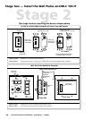
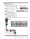
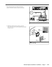
RS-232 to projector
RS-232 connection
Terminal RS-232 Cable color Pin
Tx White 2
Rx Violet 3
Ground Shield 5
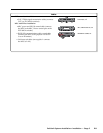
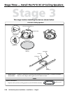
Terminal IR/RS-232
Cable color
IR Cable color
Ground
Black Black
IR Signal Red White/Black
+12V OUT
PWR SNS
GROUND
GROUND
GROUND
Tx
Rx
HOST/
CONFIG
PROJECTOR
RS-232/IR
Tx/IR
Rx
N White, Violet, an
d
Shield Not Used
Red
Black
Projector
MLC IR/RS-232
Comm Cable
IR Emitter
Connecting IR Cable
White
(or striped)
Black
Red
Black
9-Pin Female
White
Violet
Shield
+12V OUT
PWR SNS
GROUND
GROUND
GROUND
Tx
Rx
HOST/
CONFIG
PROJECTOR
RS-232/IR
Tx/IR
Rx
MLC 104 IP Plus
N Red and Black
Not Used
Connecting RS-232 Cable
Projector
MLC 104 IP Plus
Right Side Panel
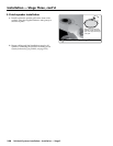
To projector
Ground ( )
IR Signal
Unidirectional IR Output
via White Striped Wire
IR Emitter
100'
(30.5 m)
GROUND
IR OUT
Tx
Rx
DISPLAY
RS-232/IR
IR connection
Black
Black
Red