


PoleVault Systems Installation • Installation — Stage 4
2-22
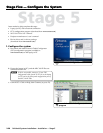
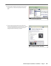
Installation — Stage Four, cont’d
N
The installation must conform to national and local
electrical codes, and UL requirements. Refer to the
device’s user manual for details.
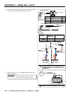
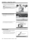
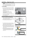
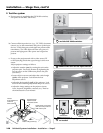
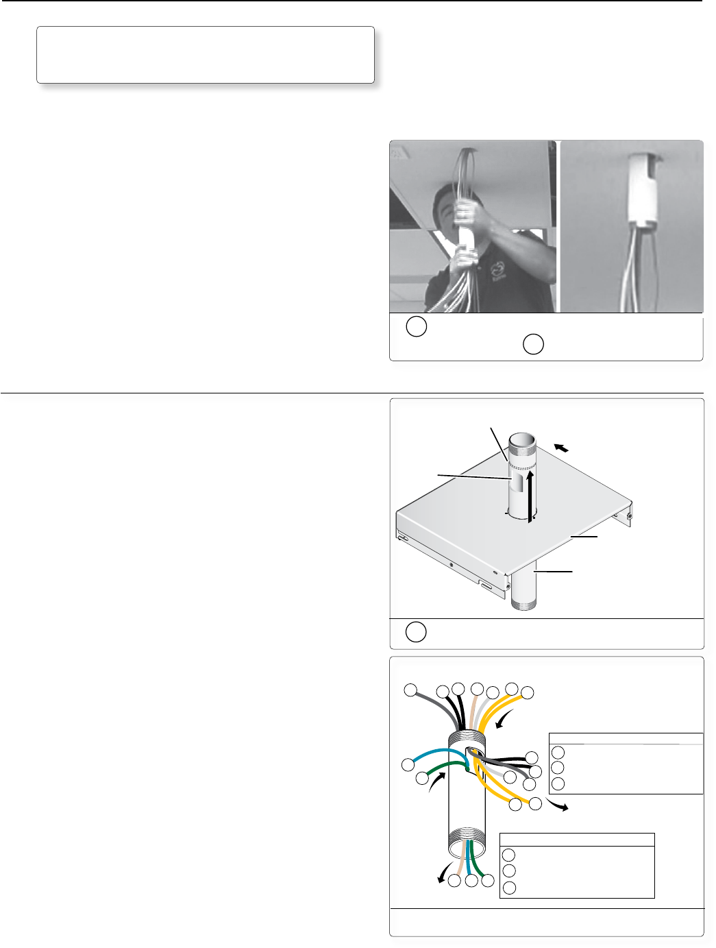
1. Pull the cables
a. Loosen the PCM 240 set screws and remove the PMP.
b. Gather all the cables from the speakers, A/V wall plates,
MLC 104 IP Plus controller, and any optional devices
installed that have been run to the projector location,
and pull them down through the hole in the ceiling tile.
These cables are:
the MLC power/RS-232 cable,
the CAT 5 input cables from the wall plates,
the speaker cables,
the MLC to projector IR/Serial comms cable,
any optional device cables (e.g. PPC 25 sensor)
c. Gather the cables together below the suspended ceiling
and pass them down the PMP.
d. Screw the PMP back up into position and tighten the set
screws on the PCM 240.
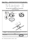
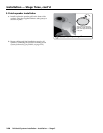
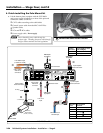
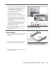
2. Install the PMK 450 Pole Mount kit
a. Remove the front and rear plates from the PMK 450,
remove the side screws, and slide the top plate forward
and away from the base plate lugs.
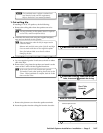
b. Slide the PMK 450’s top plate up the projector pole until
it is located just above the cable access hole.
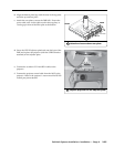
c. Level the plate and secure it in place with the four set
screws located on the collar, ensuring that a minimum
of three set screws are tightened firmly against the pole.
Rotate the pipe if necessary to achieve this.
d. Pull the CAT 5 cables from the wall plates, the speaker’s
cable, and the MLC control cable through the access hole,
ready for connection to the switcher. Leave the MLC to
projector serial communications cable to hang out of the
bottom of the pipe.
e. Insert the output video signal cables (VGA and RCA)
into the access hole and pull them down the pipe so
one end hangs out the pipe with the MLC to projector
communication cable. These cables connect to the
projector later.
PMK 450
Top Plate
PMP
Projector pipe
Cable access
hole
Slide the top cover upwards until it is located
just above the cable access hole.
Front
(towards screen)
1c
Gather the cables, pass them down
the PMP and
1d
screw it into place.
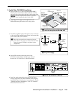
1
1
1 2
3
4
4
5
6
1
3
4
4
2 5 6
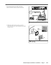
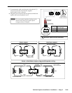
To Projector
To PVS 204SA
Cables from
PVS 204SA
Cables from A/V wall plates, MLC 104 IP Plus,
and SI 3CT LP speakers.
1
1
1
3
4
SI 3CT LP speaker cables
MLC 104 IP Plus switcher control cable
A/V wall plate cables, RGB (2), Video (1)
2
MLC 104 IP Plus projector control cable
5
6
VGA cable
Video cable
Cables to Projector
Cables to PVS 204SA
Switcher and projector cable overview
2b
Slide the top plate up onto the pole