


2-29
PoleVault Systems Installation • Installation — Stage 5
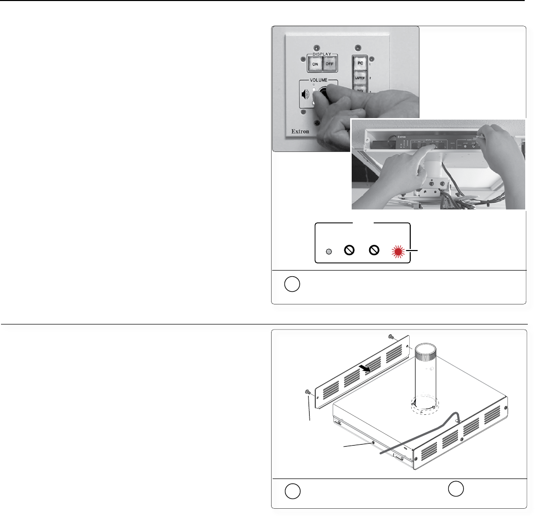
2e
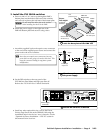
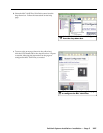
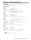
Set MLC volume to maximum, and adjust
the level on the switcher
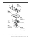
FRONT
REAR
Front
Plate
Cable from
power source
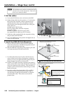
Tighten Front and
Rear Plate Screws (4)
and Side Screws (2)
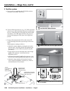
3a
Replace the front plate and
3b
tighten
down the screws on the mounting kit
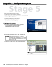
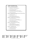
d. Test the controller’s configuration with the following:
• Check that the MLC is controlling the PVS 204SA
switcher and projector, and does output the
correct image when switching inputs.
• Check the projector’s power control (turn it off
and on at the MLC controller).
• Adjust the conguration as necessary.
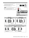
e. Adjust the audio input sensitivity as follows:
• Ensure there is an audio source at each transmitter.
• Set the MLC controller’s volume to maximum.
• On the PVS 204SA switcher, press and hold the
selected input buttons for 3 seconds. The input’s
LED will blink.
• While holding the input button in, rotate the level
encoder until the clip LED blinks, then turn the
encoder back down until the blinking stops.
• Repeat Step e for all inputs.
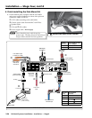
f. If necessary adjust the amplifier level by rotating
the same encoder used in Step e.
g. If necessary set the Aux/Mix level by rotating the
Aux/Mix encoder.
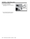
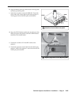
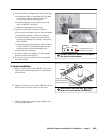
3. Final installation
a. Replace the front plate of the PMK 450. The power
cable exits the unit through the power cable access
slot at the rear.
b. Tighten down all six screws on the PMK 450, four on
the front and rear plates, and two on the sides.
c. Check and tighten the adjuster plate locking screws
on the projector bracket.
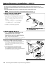
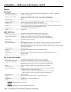
MIN/MAX CLIP
AUX/MIX LEVEL
AUDIO
This LED flashes when the
amplifier output is clipping.