


PoleVault Systems Installation • Installation — Stage 5
2-28
Installation — Stage Five, cont’d
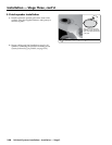
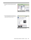
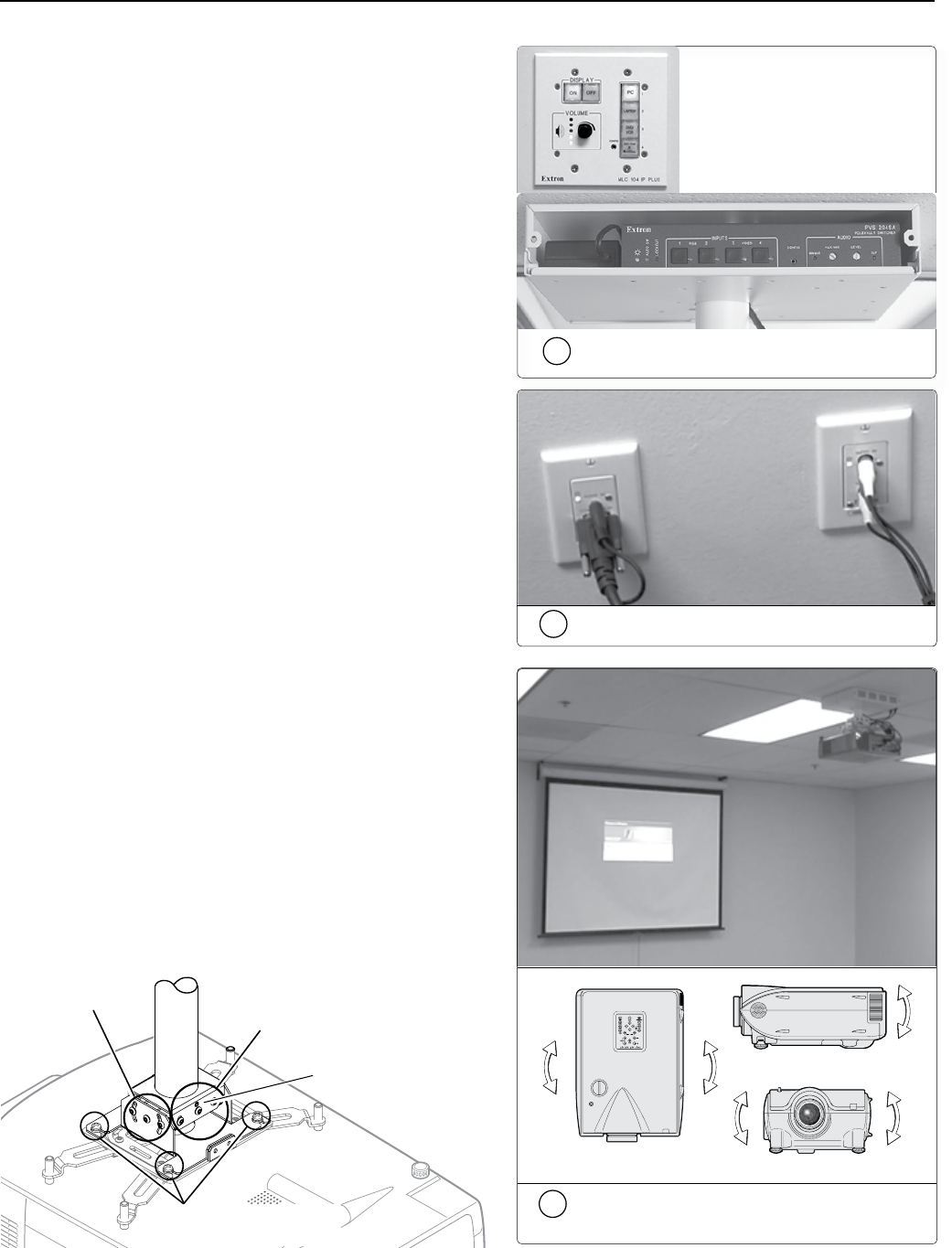
2c
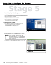
Check that an image is present, adjust
as needed.
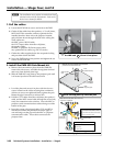
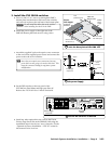
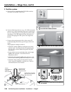
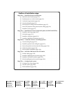
2. Test the system
a. Ensure power is supplied to the PVS 204SA switcher,
and power on the MLC 104 IP Plus.
b. Connect all the input devices (e.g., PC, DVD, document
camera, etc.) to the transmitters and power up the input
devices. Check that power and signal are present at the
transmitters. The LEDs light red when only power is
present and light green when power and a signal are
present.
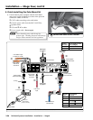
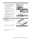
c. Power on the projector and with a video source (PC
or DVD playing) check that a good image is shown on
screen.
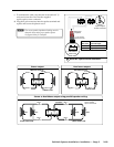
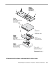
Adjust projector settings as follows:
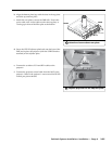
• Adjust the rotation (yaw) by turning the unit on the
projector pole. Secure the location by tightening the
two set screws on the UPB mount plate to the pole
(see below).
• Loosen all pivot screws and adjust the vertical angle
(pitch) of the projector. Lock down the four
adjustment screws.
• Adjust the horizontal tilt (roll) of the projector. Lock
down all the remaining adjustment and pivot screws.
• Adjust the image settings on the projector (zoom,
focus, keystone, brightness, contrast, etc.). Refer to
the manufacturer’s user manual.
Vertical
Angle Adjustment
and Pivot
Point Screws
Horizontal Angle
Adjustment and
Pivot Point Screws
Adjuster
Plate Locking Screws (4)
Tighten these 2 set screws
(one each side) to lock the
UPB onto the pole.
2a
Turn on the MLC 104 IP Plus controller
and the PVS 204Sa switcher
2b
Connect and turn on the input devices
Pitch/Vertical Angle
Y a w/Rotation
Roll/Tilt
Pitch/Vertical Angle
Y a w/Rotation
Roll/Tilt