


2-13
PoleVault Systems Installation • Installation — Stage 2
4. Install MediaLink Controller
T
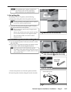
Before cabling and installing the MLC 104 IP Plus,
locate and write down the MAC address of the device
for configuring the IP address. The 12 character
alphanumeric address (e.g., 00-05-A6-03-9G-H4)
can be found on a label on the rear of the controller.
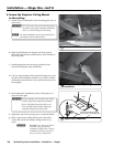
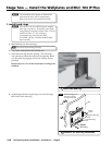
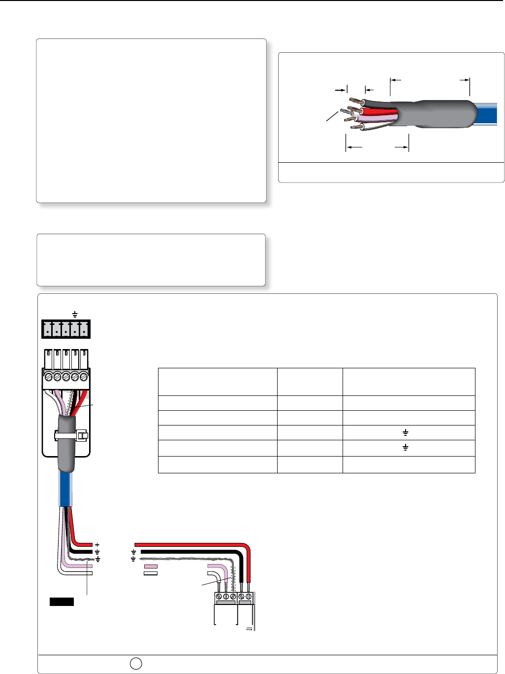
T
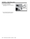
The length of exposed wire is critical to avoid
transmission problems. Ensure the lengths given
here are adhered to when stripping the cables for
connection.
N
If a drain wire is used, both ends of the
wire must be covered by heat shrink to
avoid accidental grounding.
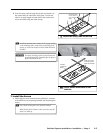
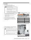
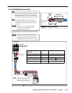
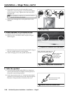
a. Connect the MLC power and RS-232 control cable as
shown.
N
The MLC 104 IP Plus is powered from the
PVS 204SA. DO NOT connect an external
power supply to the MLC 104 IP Plus unless
installing an optional secondary control panel.
MLC's MLS and
Power ports
PWR
12V
MLS
RS-232
GROUND
GROUND
A B
Tx
Rx
+12V IN
Ground ( )
+12 VDC
Tr ansmit (Tx)
B
Receive (Rx)
A
Tr ansmit (Tx)
Heat Shrink
over Drain Wire
Receive (Rx)
B
A
NOTE If you use cable that has a drain wire, tie
the drain wire to ground at both ends.
Apply heat shrink cover to both ends of the
wire to avoid accidental grounding.
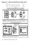
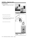
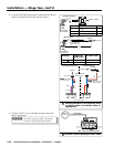
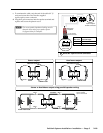
RS-232/MLC/IR
PVS 204SA
Switcher's rear panel
RS-232/MLC/IR port
ABCDE
Tx Rx IR
+12V
Ground ( )
Heat Shrink
over Drain Wire
4a
Connecting the MLC to the switcher
From MLC 104 IP Plus
terminal
Wire color To PVS 204SA terminal
A - (Rx on the MLS port) White A - (Tx on the RS-232 port)
B - (Tx on the MLS port) Violet B - (Rx on the RS-232 port)
MLS RS-232 Ground Drain wire
D - Ground
Power Ground Black
D - Ground
12 V In Red E - +12 V
Wire Bared
3/16"
(5 mm)
Max.
7/8"
(22 mm)
Heat Shrink on
Outer Jacket to
Inner Conductor
Transition
Heat Shrink on
Drain Wire
T Wire stripping lengths