


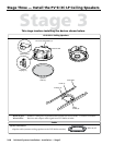
2-21
PoleVault Systems Installation • Installation — Stage 4
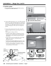
Stage 4
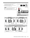
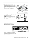
This stage covers installing the devices shown below.
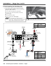
LR
AUX/MIX IN
1B
1A
I
N
P
U
T
S
O
U
T
P
U
T
S
2B
2A
4
3
RS-232 MLC/IR
DC VOL
4/8
Ohms
AMPLIFIED OUTPUTS
VOL/MUTE
Tx
ABC
RxIR 12V
10V
POWER
12V
3A MAX
US
LISTED
17TT
AUDIO/VIDEO
APPARATUS
®
RGB
VIDEO RGB
VIDEO
STEREO
ON
DUAL
MONO
HIGH
PA SS
FILTER
OFF
ON
1A
32A
1A
32A
1B
42B
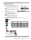
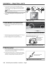
PVT RGB D
Input
Power Supply
Connector
PVT CV D
Input
RGB
Output
Video
Output
Speaker
Output
MLC Control
Port
Aux/Mix
Input
Plenum Rated UL 2043
Suitable for Use in Air-Handling Spaces
III IIIIII IIIII IIIIII IIIII
S/N A024ERD56 E 235411 WO564871-12
PVS 204SA PoleVault Switcher
DO NOT GROUND
OR SHORT
SPEAKER OUTPUTS
PVS 204SA PoleVault Switcher
PVS 204SA
POLEVAULT SWITCHER
INPUTS
12
RGB
MIN/MAX CLIP
CONFIG
AUX/MIX
LEVEL
3 4
VIDEO
AUTO SW
LOCKOUT
AUDIO
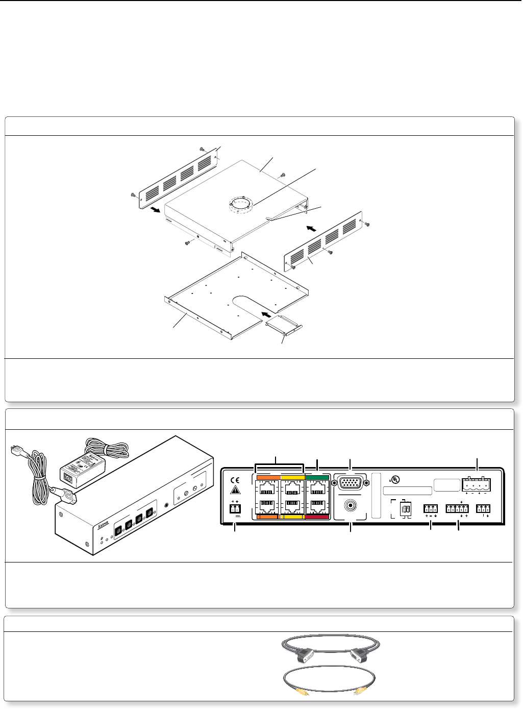
Rear View
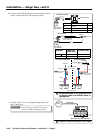
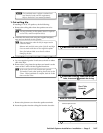
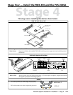
Pipe Collar (1) with
Set Screws (4)
Security Screws (2)
AC Power Cord
Access Slot
Plate
Screws (2)
Bottom Plate (1)
Filler Plate (1)
Front Plate (1)
Rear Plate (1)
Top Plate (1)
PMK 450 Pole Mount Kit
Where it goes: Attaches to PMP around cable access hole, above the projector.
What it does: Supports and hides the installed PVS 204SA switcher, power supply, and any installed optional
accessories.
Where it goes: PVS 204SA and power supply install on the base plate of the PMK 450.
What it does: Receives input video and audio signals from A/V source input wall plates, outputs and switches
the signals to projector and ceiling speakers.
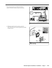
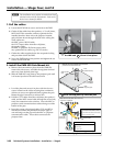
Stage Four — Install the PMK 450 and the PVS 204SA
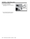
Power Supply and Cable
VGA cable (connects to RGB output and projector)
RCA cable (connects to video output and projector)
Cables
MVGA M-M, 3’
V RCA, 3’