


2-11
PoleVault Systems Installation • Installation — Stage 2
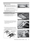
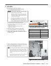
2. Pull cables
The following cables need to be installed:
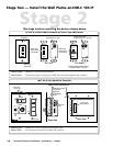
• CAT 5 cables for signal transmission from the
A/V Wall plates to the PVS 204SA.
N
For PVT RGB D Wall plates, two CAT 5 signal
cables for each input are needed.
Maximum distance from the PVS 204SA to the
Wall plates is 100 feet. The optimum distance
is between 50 and 75 feet.
The CAT 5 cables supplied are terminated to the
TIA 568A standard. Other CAT 5 cables can
be used if they are TIA 568A or 568B standards
and terminated to the same standard at both ends.
• CAT 5 cables for MLC network connection
• PoleVault switcher communication cable from the
MediaLink controller
• Projector communication cables from the
MediaLink controller.
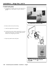
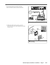
a. Drill cable pathways through any obstructions
(e.g., wall caps, fire-breaks, or horizontal studs).
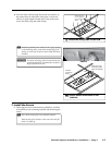
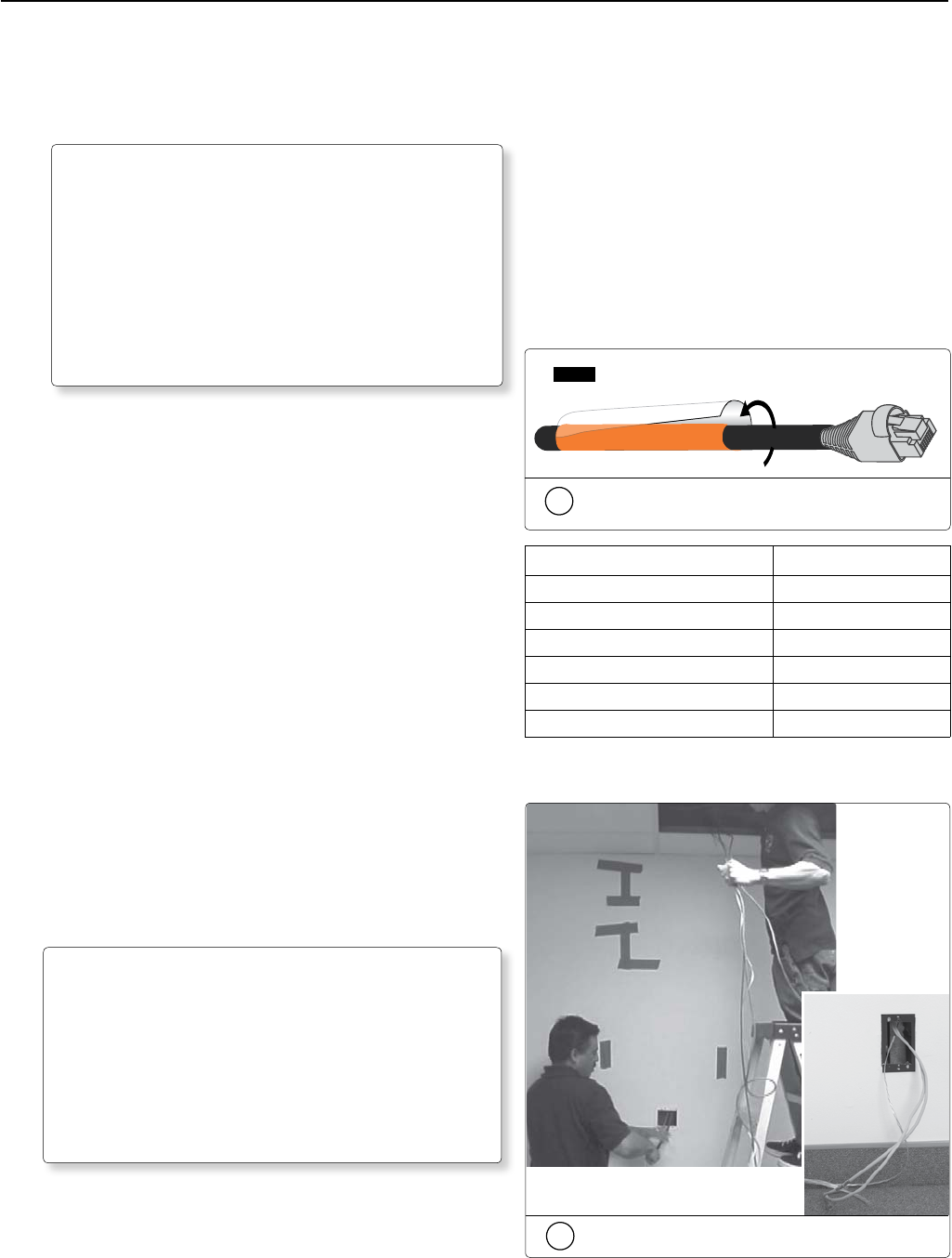
b. Label the CAT 5 signal cables at both ends with the
supplied labels. Refer to the PVS 204SA User’s Manual
for labeling details.
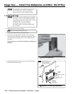
c. Pull the cabling through the wall from the ceiling space
down to the location of the transmitters and other wall
devices, and out through the openings.
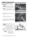
T
Secure cables with cable clamps to provide strain relief.
Trim back the outer foil shield to the point where the
cable exits the cable clamp, and insulate exposed cable
shields with heat shrink to reduce the chance of short
circuits.
Both braided and foil shields should be connected to an
equipment ground at the other end of the cable.
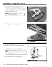
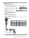
RGB #1A
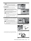
NOTE Fasten the colored section to the cable first,
then wrap the clear section around it.
2b
Use the supplied labels for clear cable
identification during installation.
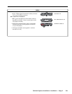
Signal Cable Label color
RGB 1A (Input 1 RGB) Orange
RGB 1 B (Input 1 RGB) Orange w/black stripe
RGB 2A (Input 2 RGB) Yellow
RGB 2B (Input 2 RGB) Yellow w/black stripe
Video 3 (Input 3 Composite Vid) Green
Video 4 (Input 1 Composite Vid) Red
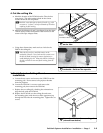
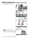
2c
Pull the cables at each location.