


PoleVault Systems Installation • Installation — Stage 2
2-8
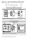
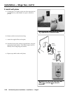
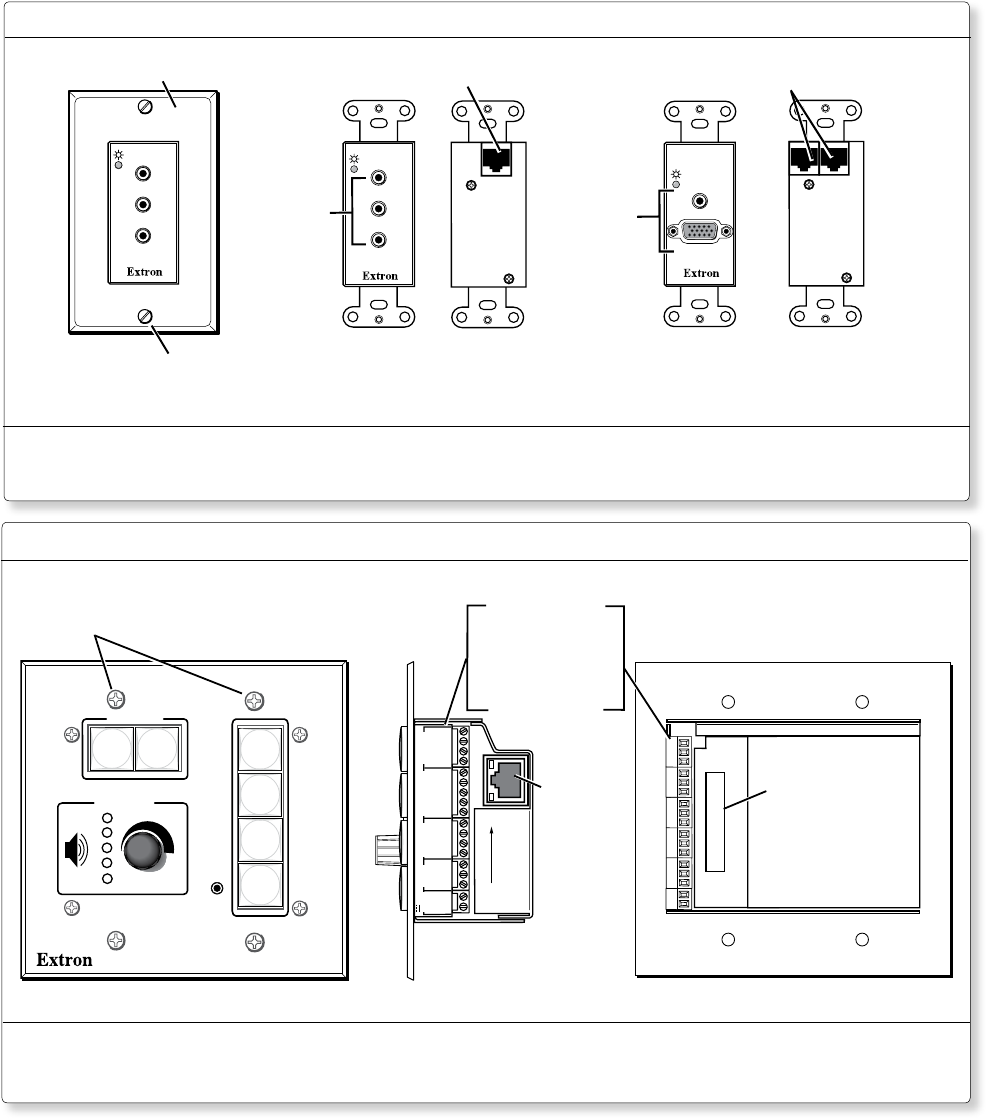
Stage Two — Install the Wall Plates and MLC 104 IP
Stage 2
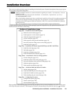
This stage involves installing the devices shown below.
AUDIO IN
L
R
VIDEO IN
Audio and
Video input
connectors
Audio and Video
output port (at rear)
PVT CV D
AUDIO IN
L
R
VIDEO IN
Mounting
screws (2)
Decora
Faceplate
COMPUTER IN
AUDIO IN
Audio and
Video input
connectors
Audio and Video
output ports (2* - at rear)
* Each RGB wall plate needs
2 output cables, A and B.
PVT RGB D
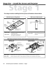
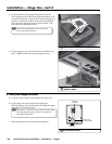
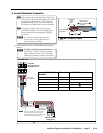
PVT CV D and PVT RGB D PoleVault A/V Source Input Wall Plates
Where it goes: Installs in a wall near input location.
What it does: Transmits an input’s composite or RGB video and audio signals to the switcher.
CONFIG
DISPLAY
VOLUME
MLC 104 IP PLUS
ON
VCR
DVD
PC
OFF
1
2
3
4
Mounting
screws (4)
1
2
3
GROUND
+12V OUT
CM
GROUND
IR OUT
GROUND
SCP
GROUND
Tx
Rx
DISPLAY
RS-232/IR
A B C D E
COMM LINK
LAN
PRESS TAB WITH
TWEEKER TO REMOVE
A B
MLS
RS-232
POWER
12V
DIGITAL
I/O
IR IN
Tx
GROUND
Rx
+12V IN
Right Side
Ethernet
port
Display/RS-232/IR
Comm. Link
Digital I/O,
MLS/RS-232
Power
RUN
100
00-05-A6-01-6B-F5
Location of
MAC address
Rear View
Captive screw connectors for:
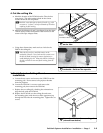
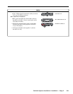
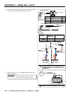
MLC 104 IP Plus MediaLink Controller
Where it goes: Installs in a wall at a location convenient to user.
What it does: Provides remote control of switcher and projector.