


General Information
M9328MX21ADSE User’s Manual, Rev. A
1-4 Freescale Semiconductor
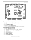
• P8 — 5.0-volt input power connector
• P9 — RJ-45 Ethernet connectors
• P10 — Line In to audio CODEC
• P11 — Microphone In to audio CODEC
• P12 — Headphone Out to audio CODEC
• P13 — TV Encoder connector
• PE1 — Connector to an Image Sensor card
• PE2, PE3 — I/O Extension connectors
• S1 — Peripheral enable and JTAG select DIP switches
• S2 — Boot mode, clock mode, and user defined DIP switches
• SW1 — Power switch
• SW2 — Reset switch
• LED1 — 5 volt power LED (green)
• LED2 — 3 volt power LED (green)
• LED3 and LED4 — General-purpose LEDs (orange)
• LED5, LED6 — Ethernet activity LEDs (green, orange)
• LED7 — external bus activity LED (red)
• U16 — IrDA transceiver
• VR1 — emulate the battery voltage level
• J3, J4, J5 and J6 — Modem control enable jumpers for RS-232 DTE interface on P2
• J7 — One wire interface
1.5 ADS Specifications
Table 1-1 shows M9328MX21ADSE specifications.
Table 1-1. Specifications
Characteristic Specifications
Clock speed (SDRAM/FLASH) CPU 266MHz, System 133MHz
Ports 10Base-T (RJ-45), RS-232 serial, USB OTG
Temperature:
operating
storage
0° to +50° C
-40° to +85° C
Relative humidity 0 to 90% (noncondensing)
Power requirements 4.5V
— 5.5 VDC @ 2.4 A
Dimensions 7.15 x 9.45 in (18.2 x 24.1 cm)