


M9328MX21ADSE User’s Manual, Rev. A
Freescale Semiconductor 1-1
Chapter 1 General Information
1.1 Description
The M9328MX21ADSE helps you develop applications for the i.MX21 MCU.
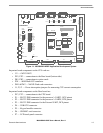
The ADS has 19 connectors and sockets that support application software, target board debugging, and
optional circuit cards. A separate LCD display panel and a separate keypad are supplied with the ADS.
When you connect the LCD panel and keypad to the ADS Base board, they align with each other.
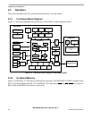
1.2 M9328MX21ADSE Features
ADS features include:
• i.MX21 Multimedia Application Processor
• Two clock-source crystals, 32.768 KHz and 26 MHz
• Power connector for +5.0-volts in from an external regulated power supply, an in-line fuse, and a
power on/off switch.
• Voltage regulators that step down the 5.0 VDC input to Vcc (3.0 VDC), 2.5 VDC, 1.8 VDC and
1.5 VDC
• Multi-ICE debug support
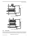
• Two 8 MB × 16-bit Burst Flash memory devices configured as one 32 MB, 32-bit device
• Two 16 MB × 16-bit SDRAM devices configured as one 64 MB, 32-bit device
• High speed expansion connectors for adding optional cards.
• Two-board system: modular CPU board plugs into Base board; Base board has connections for
LCD display panel and keypad
• Memory mapped expansion I/O
• Software readable board revisions
• Configuration and user definable DIP switches
• SD/MMC memory card connector
• Two RS-232 transceivers and DB9 connectors (one configured for DCE and one for DTE
operation) supporting on-chip UART ports
• External UART with RS-232 transceiver and DB9 connector
• IrDA transceiver that conforms to Specification 1.4 of the Infrared Data Association
• USB OTG (On The Go) interface transceiver and USB mini AB connector
• Separate LCD panel assembly that connects to the Base board and interfaces directly with the ADS
• Touch panel controller for use with the LCD
• Separate keypad unit with 36 push button keys