


Configuration and Operation
M9328MX21ADSE User’s Manual, Rev. A
2-12 Freescale Semiconductor
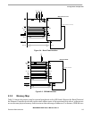
2.3.11 Audio Indicator (Buzzer)
The ADS includes an audio indicator or buzzer, U23. When S1-6 is ON, the PWMO pin of the i.MX21
controls this function. This buzzer operates from 1 KHz to 10 KHz. The maximum sound level is reached
when the frequency is 3 KHz and the duty cycle is 50%.
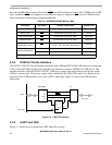
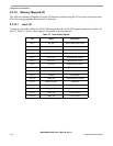
2.3.12 LED Indicators
Table 2-9 shows the ADS LED indicators and their associated functions.
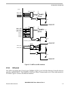
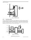
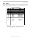
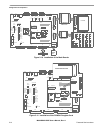
2.4 Using The Board Connectors
Table 2-10 shows the ADS connectors and functions, as well as special instructions for using the
connectors. Figure 1-1 in Chapter 1 shows the connector locations and reference designators.
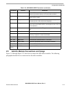
Table 2-9. Function of LED Indicators
Reference # Color Name Function
LED1 Green 5V PWR 5 V power is ON
LED2 Green VCC PWR 3 V power is ON
LED3 Orange STAT 2 User status controlled by Output BIT 15*
LED4 Orange STAT 1 User status controlled by Output BIT 14*
LED5 Green ACTIVE Blinking indicates LAN Activity
LED6 Orange LINK Link good or host controlled output
LED7 Red BUS ACT Blinking indicates external bus activity
* A logic high level at the controlling pin turns on the LED. A logic low turns it off.
Table 2-10. M9328MX21ADSE Connectors
Connector Function Comments
P1 UART1 RS-232 DCE interface to UART1 of the i.MX21
P2 UART4 RS-232 DTE interface to UART4 of the i.MX21
P3 External UART RS-232 DCE interface to Port A of the ST16C2552 UART
P4 USB OTG USB On The Go mini AB connector
P5 Keypad module Connect the Keypad ribbon cable between this connector and the
corresponding connector of the Keypad Module, J1.
P6 SD/MMC Slide the MMC card into the connector until it snaps into place.
P7 LCD panel Connect LCD ribbon cable between this connector and the
corresponding connector of the LCD display panel, J11.
P8 Power Plug the 5-volt power-supply jack end into this connector.